ESP32-CAM
A Wi-Fi camera on a board the size of a postage stamp. The ESP32-CAM combines an ESP32, an OV2640 2 MP camera, 4 MB PSRAM and a microSD slot for a few dollars. This guide covers the front and back of the board, the full 16-pin pinout, the camera pin map, how to program it with an FTDI adapter or the ESP32-CAM-MB, which pins are free, microSD, power and brownout fixes, live video streaming, and code with projects.
Complete Learning Path — ESP32-CAM
From board anatomy and the full pinout, to the camera pin map, programming, free pins, microSD, power, video streaming, antenna, code and projects
What is the ESP32-CAM?
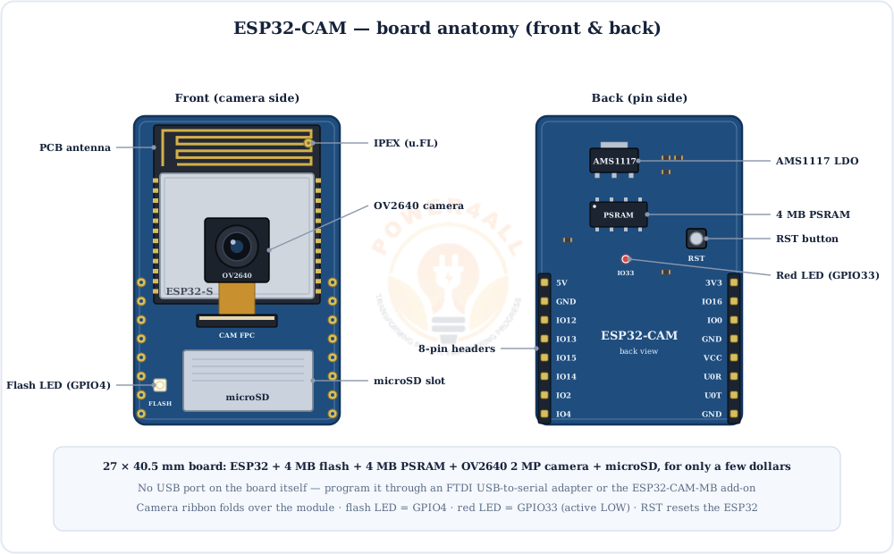
The ESP32-CAM is a tiny Wi-Fi camera board. On 27 × 40.5 mm it packs an ESP32 (dual-core, 240 MHz, Wi-Fi + Bluetooth), 4 MB PSRAM for image buffers, an OV2640 2-megapixel camera, a microSD slot and a bright flash LED.
It is the cheapest way to build an IP camera, a doorbell cam, a time-lapse recorder or a motion-triggered photo trap. The catch is that it has no USB port and only a few spare pins, and it needs a solid 5 V supply. This guide covers all three.
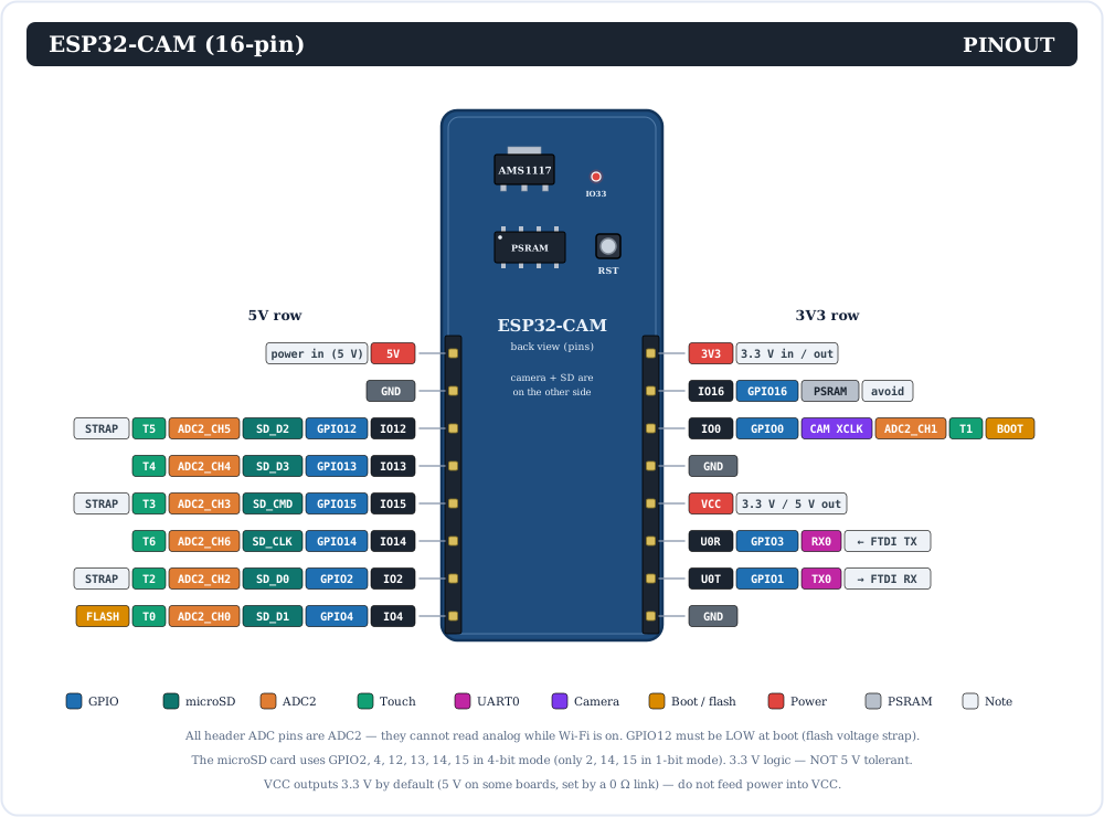
Full ESP32-CAM Pinout
The complete ESP32-CAM pinout: all 16 header pins, printed on the back of the board, with each pin's GPIO number, microSD signal, ADC2/touch channel and special role.
At a glance, here is what those 16 pins are for:
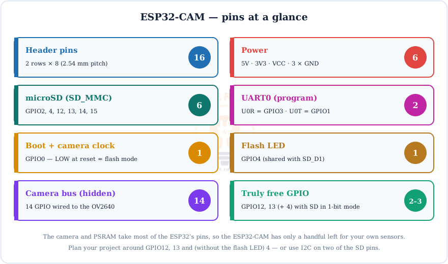
Every Pin Explained
| Pin | GPIO | What it does / watch out for |
|---|---|---|
| 5V | — | Main power input. Feed a stable 5 V (2 A supply recommended). |
| 3V3 | — | 3.3 V rail. It can power the board at 3.3 V, but 5 V on the 5V pin is far more reliable. |
| VCC | — | Output, 3.3 V by default (5 V on some boards). Don't feed power in here. |
| GND | — | Three ground pins. |
| U0R / U0T | 3 / 1 | UART0 RX/TX: connect to the FTDI's TX/RX to upload and for the Serial Monitor. |
| IO0 | 0 | Boot pin: LOW at reset = flash mode. Also the camera XCLK, so leave it alone at runtime. |
| IO16 | 16 | Used by the PSRAM on most boards; avoid it. |
| IO4 | 4 | Drives the white flash LED (through a transistor) and is SD_D1. |
| IO2, IO14, IO15 | 2, 14, 15 | SD_D0, SD_CLK, SD_CMD. Needed even in 1-bit SD mode; 2 and 15 are strapping pins. |
| IO12, IO13 | 12, 13 | SD_D2/D3 in 4-bit mode, free in 1-bit mode. GPIO12 must be LOW at boot. |
No analog with Wi-Fi
Every header pin with an ADC is on ADC2, which the ESP32 cannot use while Wi-Fi is on. For analog sensors in a Wi-Fi project, use an I2C ADC module (for example ADS1115) on two free pins. Pins are 3.3 V only and not 5 V tolerant.
OV2640 Camera Pin Map
The camera plugs into a 24-pin FPC connector and uses 16 ESP32 signals: a clock, the SCCB control bus, sync lines and an 8-bit parallel data bus. These are the pins behind CAMERA_MODEL_AI_THINKER.
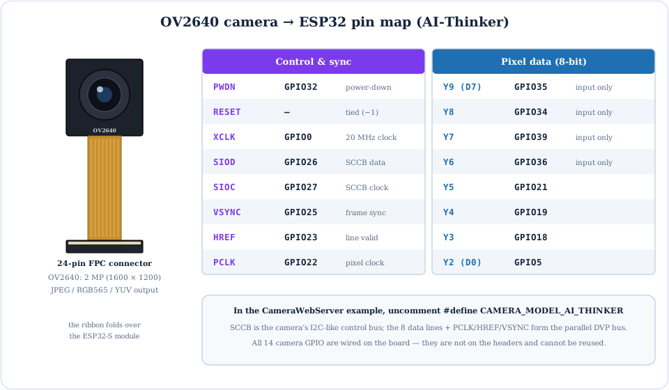
How the Board Fits Together
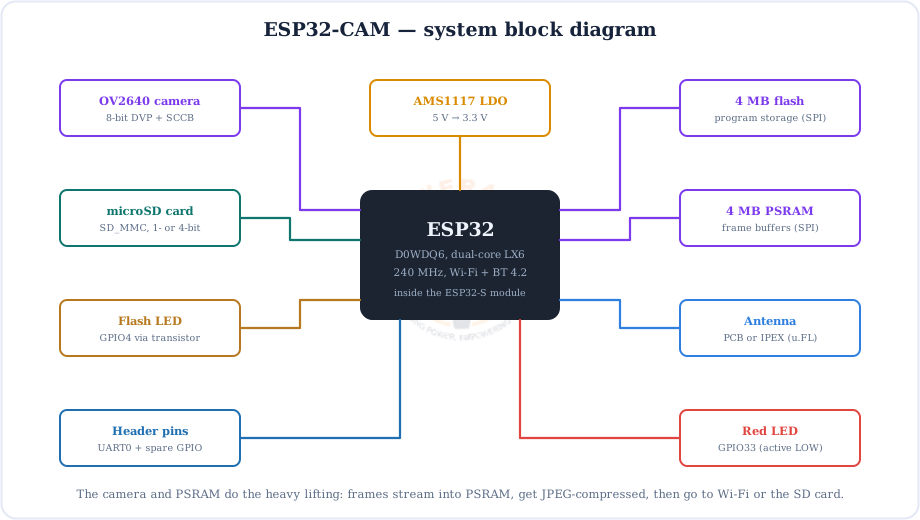
The ESP32 sits in the middle, streaming camera frames into PSRAM, compressing them to JPEG, then sending them over Wi-Fi or writing them to the SD card.
How to Program the ESP32-CAM with an FTDI Adapter
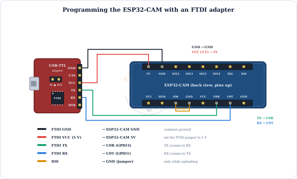
Because the board has no USB port, you upload through a USB-to-serial (FTDI) adapter. That takes four wires plus one jumper to put the chip into flash mode.
Power it from 5 V
Set the FTDI's jumper to 5 V and wire it to the 5V pin. Many FTDI boards can't supply enough current at 3.3 V, and the result is failed uploads and brownout resets.
The Easy Way: ESP32-CAM-MB
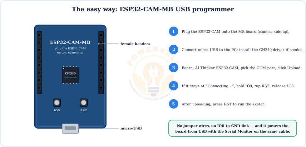
The ESP32-CAM-MB is a small shield with a micro-USB port and a CH340 USB-serial chip. Plug the ESP32-CAM on top and you get one-cable uploads and a Serial Monitor.
Upload Steps & Arduino IDE Settings
Which ESP32-CAM Pins Are Free?
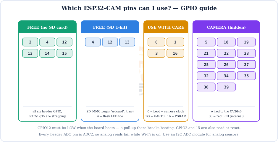
This is the most-asked ESP32-CAM question. The answer depends on whether you use the SD card:
- Need I2C? Call
Wire.begin(14, 15)(or 12/13) when you're not using the SD card. The ESP32 can route I2C to almost any pin; add pull-up resistors. - Need a button or sensor with SD? Use GPIO13 or GPIO12 with SD in 1-bit mode. Don't pull GPIO12 HIGH at boot.
- Need more pins? Add an I2C I/O expander, or choose an ESP32-S3 camera board.
microSD Card: 4-bit vs 1-bit Mode
The slot uses the ESP32's fast SD_MMC host. In 4-bit mode it takes all six header GPIO; 1-bit mode is a little slower but gives three pins back.
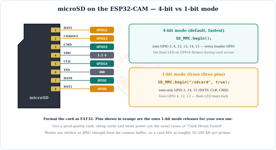
SD_MMC.begin() = 4-bit; SD_MMC.begin("/sdcard", true) = 1-bit (frees GPIO 4, 12, 13 and stops the flash LED flickering).Power Supply & the Brownout Error
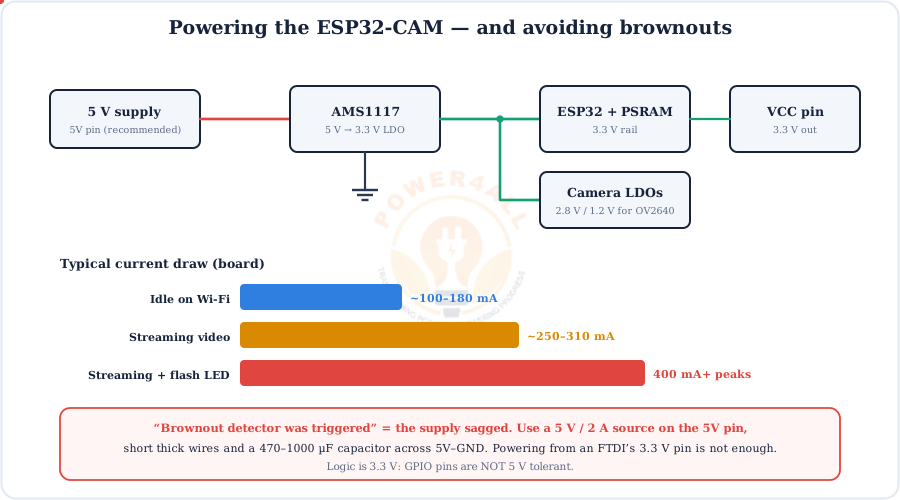
The #1 ESP32-CAM problem isn't code, it's power. The camera and Wi-Fi draw short current peaks, and a weak supply resets the board with “Brownout detector was triggered”.
Live Video Streaming (CameraWebServer)
The built-in CameraWebServer example turns the board into an IP camera you can watch from any browser on your network.
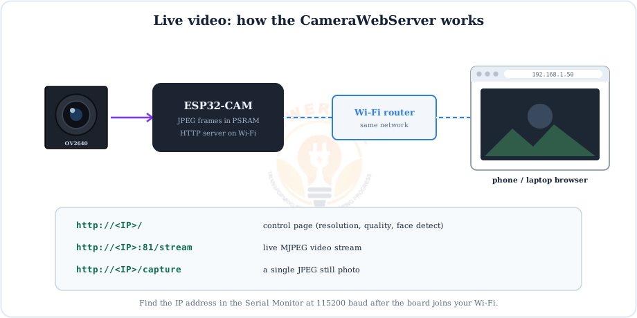
http://<IP>/, live stream at :81/stream, and a single photo at /capture.Resolutions & Image Quality
The OV2640 goes up to UXGA (1600 × 1200), but bigger frames stream more slowly. For smooth video, start at SVGA or VGA.
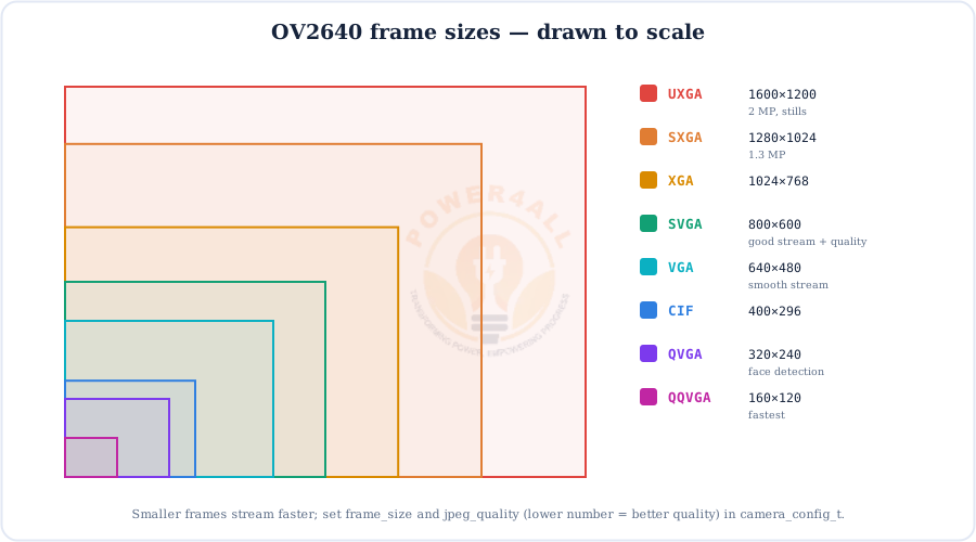
frame_size and jpeg_quality (10–63, lower = better) in camera_config_t.Using an External Antenna
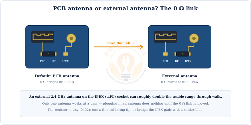
Weak Wi-Fi and a choppy stream? The module has an IPEX (u.FL) socket, but it only works once you move a tiny 0 Ω link.
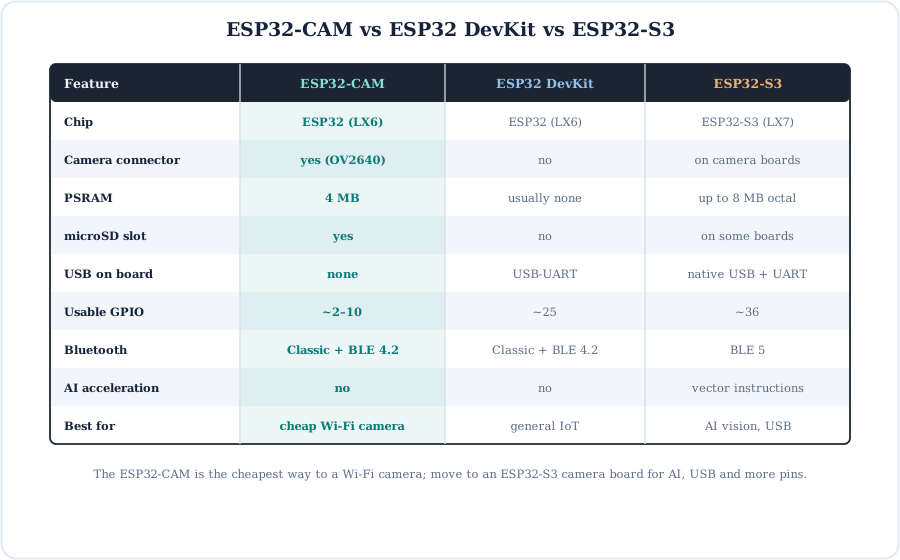
ESP32-CAM vs ESP32 DevKit vs ESP32-S3
Code Examples
Every camera sketch starts with the same pin configuration. Save Example 1 as camera_init.h and reuse it.
1. Initialise the camera (AI-Thinker pins)
#include "esp_camera.h"
bool initCamera() {
  camera_config_t c = {};
  c.ledc_channel = LEDC_CHANNEL_0;  c.ledc_timer = LEDC_TIMER_0;
  c.pin_d0 = 5;  c.pin_d1 = 18; c.pin_d2 = 19; c.pin_d3 = 21;   // Y2..Y5
  c.pin_d4 = 36; c.pin_d5 = 39; c.pin_d6 = 34; c.pin_d7 = 35;   // Y6..Y9
  c.pin_xclk = 0;  c.pin_pclk = 22; c.pin_vsync = 25; c.pin_href = 23;
  c.pin_sccb_sda = 26; c.pin_sccb_scl = 27;             // older cores: pin_sscb_*
  c.pin_pwdn = 32; c.pin_reset = -1;
  c.xclk_freq_hz = 20000000;
  c.pixel_format = PIXFORMAT_JPEG;
  c.frame_size   = FRAMESIZE_SVGA;                          // 800 x 600
  c.jpeg_quality = 12;                                     // 10-63, lower = better
  c.fb_count     = 1;
  return esp_camera_init(&c) == ESP_OK;
}
2. Blink the red status LED (GPIO33, active LOW)
void setup() { pinMode(33, OUTPUT); }
void loop() {
  digitalWrite(33, LOW);  delay(500);    // LOW = LED on
  digitalWrite(33, HIGH); delay(500);
}
3. Dim the flash LED with PWM (GPIO4)
void setup() { ledcAttach(4, 5000, 8); }    // core 3.x: pin, Hz, bits
void loop()  { ledcWrite(4, 20); }         // ~8 % brightness, very bright LED!
4. Take one photo and save it to the SD card
#include "SD_MMC.h"
// + initCamera() from Example 1
void setup() {
  Serial.begin(115200);
  if (!initCamera() || !SD_MMC.begin("/sdcard", true)) { Serial.println("init failed"); return; }
  camera_fb_t *fb = esp_camera_fb_get();                 // grab a JPEG frame
  File f = SD_MMC.open("/photo.jpg", FILE_WRITE);
  f.write(fb->buf, fb->len); f.close();
  esp_camera_fb_return(fb);
  Serial.println("saved /photo.jpg");
}
void loop() {}
ESP32-CAM Projects
Three popular builds, from a live Wi-Fi camera to a battery-friendly motion trap.
Project 1: Wi-Fi security camera (live stream)
// File > Examples > ESP32 > Camera > CameraWebServer
#define CAMERA_MODEL_AI_THINKER          // uncomment this model, comment the others
const char *ssid     = "my-ssid";
const char *password = "password";
// Upload, open Serial Monitor @115200, browse to the printed IP address
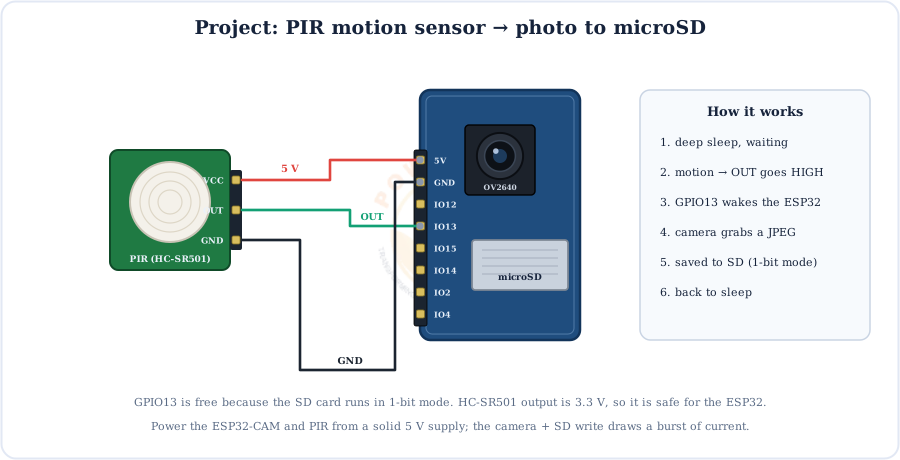
Project 2: Motion-triggered photo trap
#include "SD_MMC.h"
RTC_DATA_ATTR int n = 0;                              // photo counter survives deep sleep
// + initCamera() from Code Example 1
void setup() {
  if (initCamera() && SD_MMC.begin("/sdcard", true)) {    // 1-bit: frees GPIO13
    camera_fb_t *fb = esp_camera_fb_get();
    File f = SD_MMC.open("/pic" + String(++n) + ".jpg", FILE_WRITE);
    f.write(fb->buf, fb->len); f.close();
    esp_camera_fb_return(fb);
  }
  esp_sleep_enable_ext0_wakeup(GPIO_NUM_13, 1);           // wake when PIR goes HIGH
  esp_deep_sleep_start();
}
void loop() {}
Project 3: Time-lapse recorder
// Project 2 code, but replace the wake-up line with:
esp_sleep_enable_timer_wakeup(60 * 1000000ULL);          // 60 seconds
// Tip: the first frames after power-up can be dark/green — grab and
// discard one or two frames before saving the real photo.
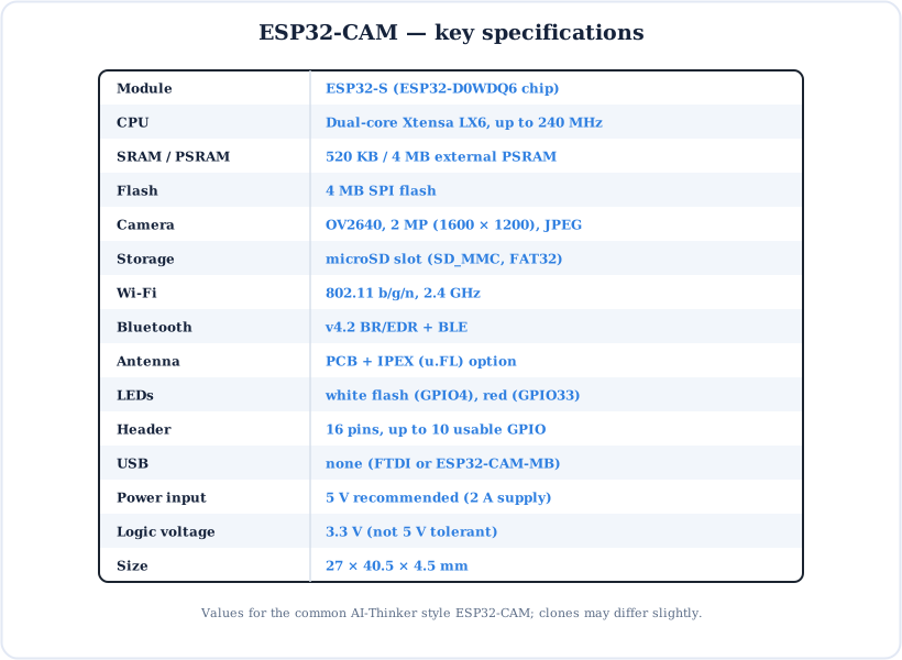
ESP32-CAM Specifications
Key Terms — Glossary
| Term | Meaning |
|---|---|
| OV2640 | The 2-megapixel image sensor with built-in JPEG compression. |
| FPC | Flexible printed circuit: the thin ribbon that connects the camera. |
| DVP | Digital video port: the 8-bit parallel camera bus plus sync lines. |
| SCCB | The camera's I2C-like control bus (SIOD/SIOC). |
| PSRAM | Extra 4 MB RAM that holds camera frame buffers. |
| SD_MMC | The ESP32's fast SD card host, in 1-bit or 4-bit mode. |
| FTDI | A common USB-to-serial (USB-TTL) adapter used to program boards without USB. |
| Flash mode | Boot mode entered when GPIO0 is LOW at reset, used for uploading. |
| Brownout | A supply dip that makes the ESP32 reset itself for safety. |
| MJPEG | “Motion JPEG”: video sent as a stream of JPEG pictures. |
| IPEX / u.FL | A tiny coaxial socket for an external antenna. |
Frequently Asked Questions
Quick answers to the questions people ask most about the ESP32-CAM.
What is the ESP32-CAM?
A low-cost ESP32 board with an OV2640 2 MP camera, 4 MB PSRAM, 4 MB flash, a microSD slot and a flash LED. It has Wi-Fi and Bluetooth, 16 header pins and no USB port, and is widely used for Wi-Fi cameras, streaming and photo projects.
How do I program the ESP32-CAM without a USB port?
Use an FTDI USB-to-serial adapter: GND→GND, VCC (5 V)→5V, TX→U0R, RX→U0T. Connect IO0 to GND, press RST, and upload with AI Thinker ESP32-CAM selected. Or plug the board into an ESP32-CAM-MB and use its micro-USB port.
Why does my ESP32-CAM say Brownout detector was triggered?
The supply dipped during a camera/Wi-Fi current peak. Use a stable 5 V supply rated about 2 A on the 5V pin, short thick wires and a 470–1000 µF capacitor across 5V–GND. Don't run it from an FTDI's 3.3 V pin.
Which GPIO pins are free on the ESP32-CAM?
The header exposes GPIO 0, 1, 2, 3, 4, 12, 13, 14, 15 and 16. Without the SD card, 2, 4, 12, 13, 14 and 15 are free; with SD in 1-bit mode, 4, 12 and 13 are free. GPIO0 is the camera clock and boot pin, 1/3 are serial and 16 is used by the PSRAM.
What camera does the ESP32-CAM use and what is the maximum resolution?
Usually an OV2640 2 MP camera with JPEG output up to UXGA (1600 × 1200). Use SVGA (800 × 600) or VGA (640 × 480) for smoother streaming.
How do I fix Failed to connect to ESP32: Timed out waiting for packet header?
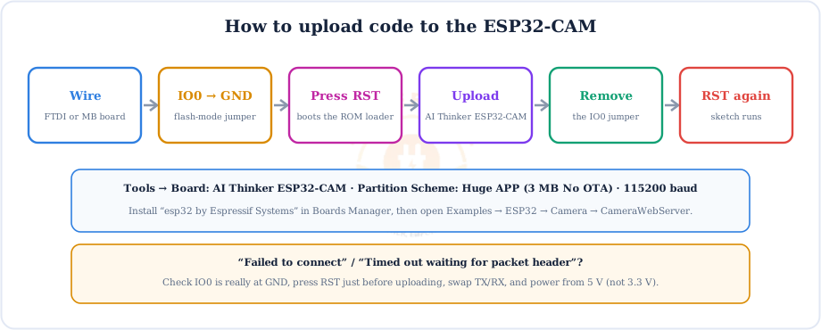
The board isn't in flash mode or the wiring is wrong. Check IO0 is at GND, press RST just before uploading, confirm TX→U0R and RX→U0T, power the 5V pin at 5 V, and try a better USB cable.
Can the ESP32-CAM use an external antenna?
Yes. Move the tiny 0 Ω resistor next to the IPEX (u.FL) socket from the PCB-antenna position to the IPEX position, then plug in a 2.4 GHz antenna.
What is the ESP32-CAM-MB?
A programmer shield with a micro-USB port, a CH340 USB-serial chip and IO0/RST buttons. The ESP32-CAM plugs on top, so you can upload and use the Serial Monitor over one cable, with no FTDI and no jumper wires.
Conclusion & Key Takeaways
The ESP32-CAM is the cheapest route to a Wi-Fi camera. Once you know its three quirks (no USB, few free pins, needs good 5 V power), it's easy to use.
OV2640
2 MP, JPEG, up to UXGA.
No USB
FTDI or ESP32-CAM-MB.
IO0 → GND
to upload, then RST.
Free pins
4, 12, 13 with SD 1-bit.
5 V, 2 A
beats brownouts.
Flash LED
GPIO4 · red LED GPIO33.