ESP32-S3
Espressif's AI-ready Wi-Fi + Bluetooth 5 microcontroller. The ESP32-S3 pairs two Xtensa LX7 cores at 240 MHz with vector instructions, native USB, 45 GPIO and up to 8 MB PSRAM. This guide covers the DevKitC-1 board, the WROOM-1 module (N16R8 decoded), a complete 44-pin pinout, which pins are safe, USB, ADC, touch, PWM, Wi-Fi, BLE, AI, deep sleep, and code examples with projects.
Complete Learning Path — ESP32-S3
From the chip and WROOM-1 module, to the full DevKitC-1 pinout, safe GPIO, power, native USB, analog, touch, PWM, buses, wireless, AI, sleep, uploading, code and projects
What is the ESP32-S3?
The ESP32-S3 is a Wi-Fi + Bluetooth 5 LE microcontroller from Espressif, and the most capable member of the ESP32 family for makers. It keeps the familiar dual-core, 240 MHz design but moves to Xtensa LX7 cores with vector instructions for AI, and adds native USB, more pins and fast octal PSRAM.
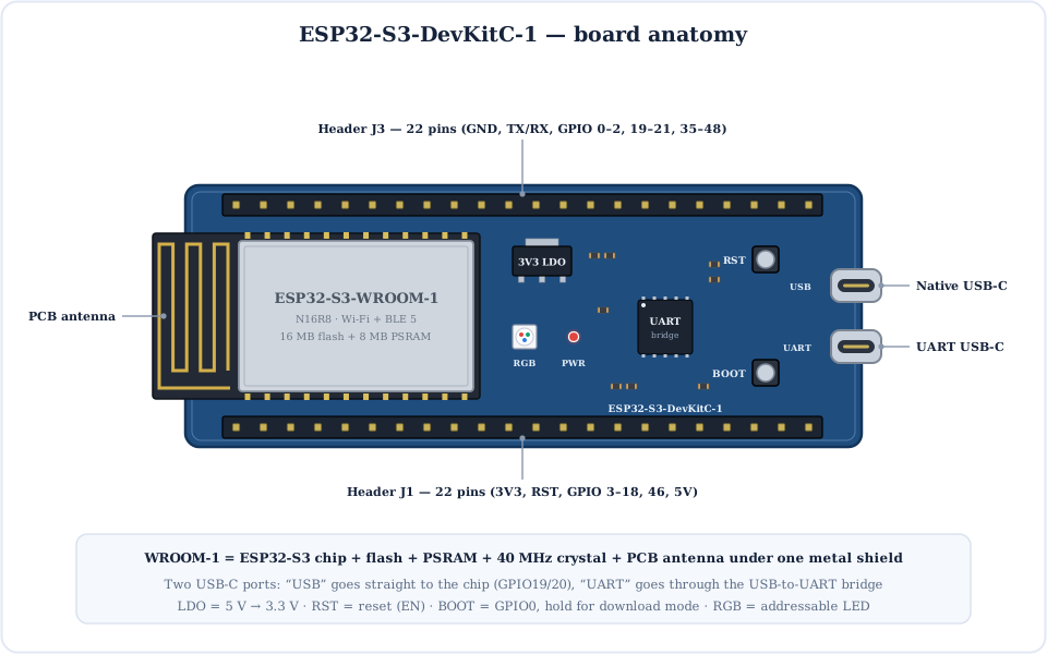
Most people meet it on the ESP32-S3-DevKitC-1 board shown below. It carries an ESP32-S3-WROOM-1 module, two USB-C ports, an addressable RGB LED and 44 header pins. It programs in the Arduino IDE, ESP-IDF or MicroPython, and is the chip behind many camera, voice and smart-display boards.
Inside the ESP32-S3 Chip
One chip holds two application cores, a low-power RISC-V co-processor, memory, a 2.4 GHz radio, crypto engines and a long list of peripherals, including USB, LCD and camera interfaces the original ESP32 never had.
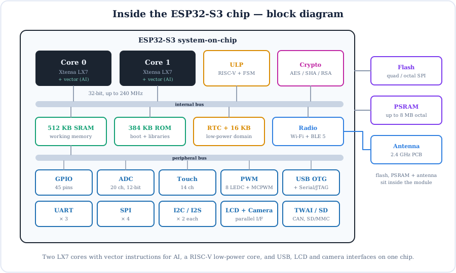
- Two Xtensa LX7 cores at up to 240 MHz. Arduino runs your
loop()on core 1 and Wi-Fi on core 0. - Vector (SIMD) instructions accelerate neural-network maths for face detection, wake words and TinyML.
- ULP co-processors (RISC-V and FSM) can read sensors while the main cores sleep.
- 512 KB SRAM + 384 KB ROM, plus 16 KB of RTC memory that survives deep sleep.
- Security: secure boot, flash encryption and AES/SHA/RSA/HMAC accelerators.
The ESP32-S3-WROOM-1 Module & What “N16R8” Means
You rarely solder the bare chip. The WROOM-1 module packs the chip, flash, PSRAM, crystal and antenna under a metal shield, and its part number tells you the memory.
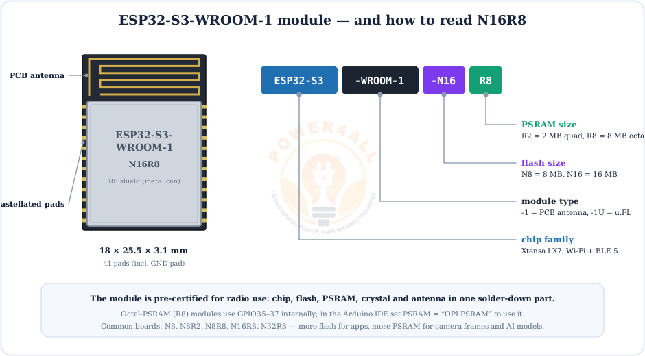
| Module variant | Flash | PSRAM | Arduino “PSRAM” setting |
|---|---|---|---|
| N8 | 8 MB | none | Disabled |
| N8R2 | 8 MB | 2 MB (quad) | QSPI PSRAM |
| N8R8 | 8 MB | 8 MB (octal) | OPI PSRAM |
| N16R8 | 16 MB | 8 MB (octal) | OPI PSRAM |
Full ESP32-S3-DevKitC-1 Pinout
Here is the complete ESP32-S3-DevKitC-1 pinout: all 44 header pins on J1 and J3, each with its GPIO number, ADC channel, touch channel and special functions (UART, I2C, SPI, USB, JTAG, strapping and PSRAM).
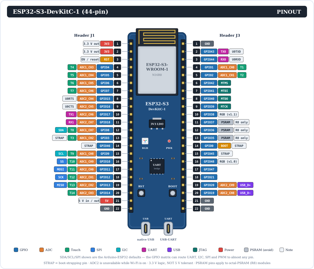
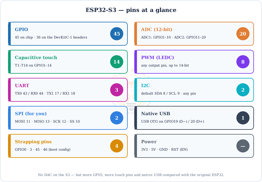
Want the short version first? These cards group the pins by job:
Every Pin Explained
The S3 has a GPIO matrix, so most functions can move to almost any pin. What follows are the fixed functions and the Arduino defaults you'll use every day.
ADC1 & ADC2
ADC1 on GPIO1–10, ADC2 on GPIO11–20. ADC2 cannot be used while Wi-Fi runs.
Touch T1–T14
GPIO1–14 are capacitive touch pads; they can also wake the chip from sleep.
UART0
GPIO43 (TX0) / GPIO44 (RX0), wired to the UART USB-C port.
I2C default
SDA = GPIO8, SCL = GPIO9 for Wire.begin().
SPI default
MOSI 11, MISO 13, SCK 12, SS 10 (FSPI) for SPI.begin().
USB D−/D+
GPIO19 / GPIO20 go to the native USB-C port.
JTAG
GPIO39–42 (MTCK/MTDO/MTDI/MTMS) for an external debugger, and free otherwise.
RGB LED
Addressable LED on GPIO48 (v1.0) or GPIO38 (v1.1): RGB_BUILTIN.
Power & control pins
| Pin | What it does |
|---|---|
| 3V3 (J1-1, J1-2) | 3.3 V from the on-board LDO, for sensors and modules. |
| 5V (J1-21) | 5 V from USB, or feed 5 V in here to power the board. |
| GND | Ground: J1-22 and J3-1, J3-21, J3-22. |
| RST (J1-3) | The chip's EN pin; pull LOW (or press RST) to reset. |
| GPIO0 / BOOT | Hold LOW at reset (BOOT button) to enter download mode. |
Which ESP32-S3 Pins Are Safe to Use?
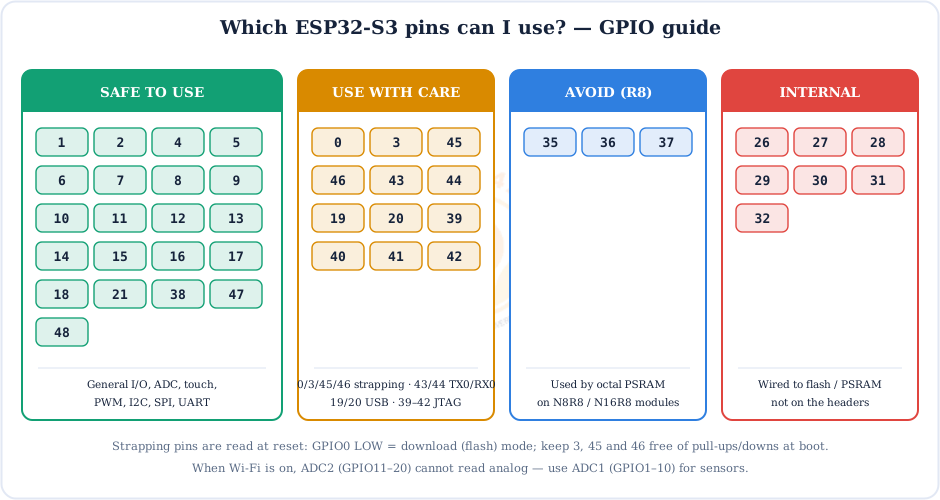
This is the question everyone asks. Some pins set the boot mode, some carry USB or serial, and some are taken by the flash and PSRAM. Here is the short answer:
Strapping pins decide how the chip boots
GPIO0 LOW at reset = download mode. GPIO3 selects the JTAG source, GPIO45 sets the flash voltage and GPIO46 controls boot messages. Don't hang pull-up or pull-down loads on them, or the board may refuse to boot.
Powering the ESP32-S3
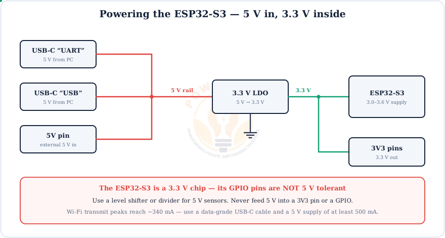
The DevKitC-1 takes 5 V from either USB-C port or the 5V pin; an LDO regulator makes the 3.3 V the chip runs on.
3.3 V logic: not 5 V tolerant
Never put 5 V on a GPIO. For 5 V sensors use a resistor divider or a logic-level shifter, and give motors or LED strips their own supply through a MOSFET.
Native USB: the S3's Superpower
Unlike the original ESP32, the S3 has USB built into the chip. That's why the DevKitC-1 has two USB-C ports.
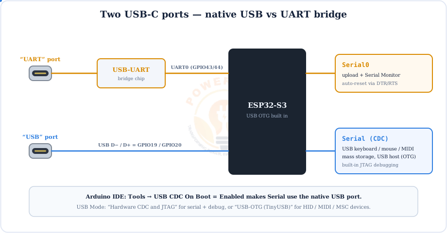
- USB CDC serial: set USB CDC On Boot = Enabled and
Serialprints over the native port. - USB devices: keyboard, mouse, gamepad, MIDI or a USB flash drive (MSC) with USB Mode = USB-OTG (TinyUSB).
- Built-in JTAG: debug with breakpoints over the same cable, no external probe needed.
ADC & Capacitive Touch
Two 12-bit ADCs give 20 analog channels, and 14 pins double as touch pads. One surprise if you're coming from the ESP32: on the S3, touch readings go up when touched.
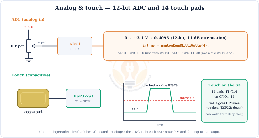
Use analogReadMilliVolts() for factory-calibrated millivolts, and keep analog sensors on ADC1 (GPIO1–10) if your sketch uses Wi-Fi. Explore bit depth with the ADC Resolution Calculator. There is no DAC on the S3; use PWM with an RC filter or an external I2S DAC.
PWM with LEDC
The LEDC peripheral gives 8 PWM channels on any output pin, with frequency and resolution you choose (up to 14 bits).
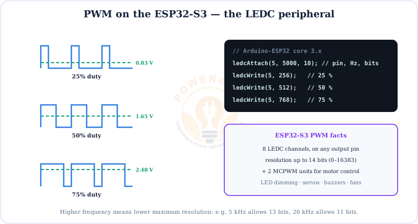
ledcAttach(pin, freq, bits) then ledcWrite(pin, duty).UART, I2C & SPI Default Pins
These are the pins the Arduino core uses when you don't specify any. Thanks to the GPIO matrix you can pass other pins to Wire.begin(sda, scl), SPI.begin(sck, miso, mosi, ss) or Serial1.begin(baud, SERIAL_8N1, rx, tx).
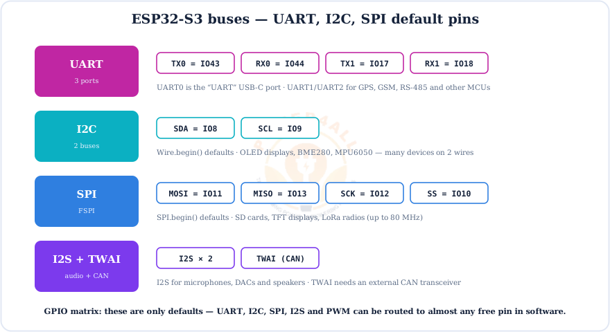
Many I2C modules need pull-ups; size them with the Pull-up Resistor Calculator.
Wi-Fi & Bluetooth 5 LE
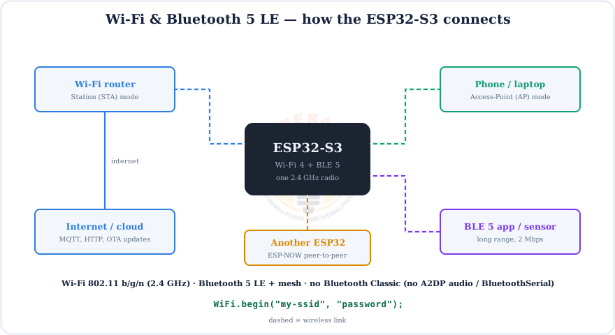
One 2.4 GHz radio handles Wi-Fi 802.11 b/g/n (station, access point, or both) and Bluetooth 5 LE with long-range and 2 Mbps modes.
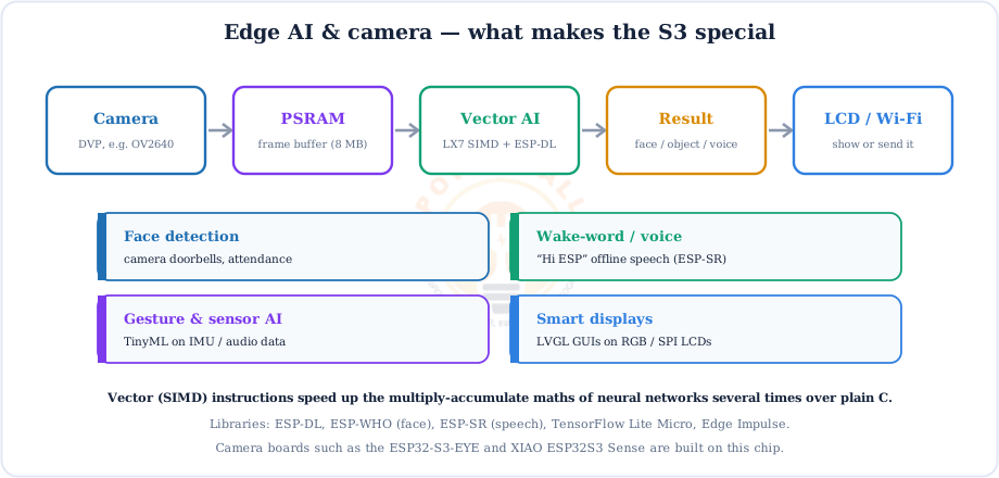
Edge AI & Camera
The feature that gives the S3 its reputation: vector instructions plus PSRAM and a camera interface let a $5 chip run small neural networks offline.
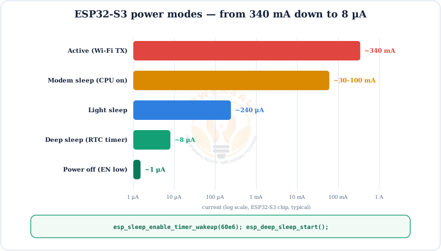
Power Modes & Deep Sleep
For battery projects, deep sleep drops the chip from hundreds of mA to about 8 µA. Wake it with a timer, a GPIO, a touch pad or the ULP co-processor.
How to Upload Code to the ESP32-S3
Install the Espressif core, choose ESP32S3 Dev Module, set flash and PSRAM for your module, and upload over either USB-C port.
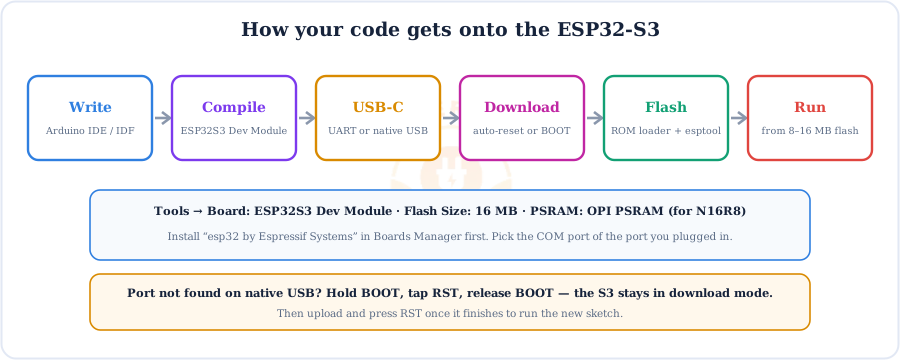
Port not showing up?
Use a data USB-C cable. On the native port, hold BOOT, tap RST, release BOOT, then upload and press RST when it finishes. If Serial prints nothing over native USB, enable USB CDC On Boot.
ESP32-S3 vs ESP32 vs ESP32-C3
Three popular Espressif chips, three different sweet spots.
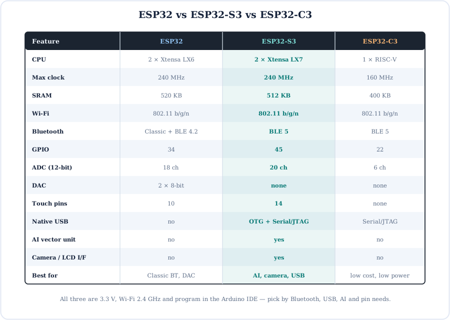
Coming from an Arduino Uno? The S3 is 15× faster with 250× the RAM and built-in wireless, but it runs at 3.3 V instead of 5 V.
Code Examples (Arduino-ESP32 core 3.x)
Five short sketches covering the features you'll use most.
1. Colour the on-board RGB LED
void setup() {}
void loop() {
  rgbLedWrite(RGB_BUILTIN, 40, 0, 0);  delay(500);   // red   (core 2.x: neopixelWrite)
  rgbLedWrite(RGB_BUILTIN, 0, 40, 0);  delay(500);   // green
  rgbLedWrite(RGB_BUILTIN, 0, 0, 40);  delay(500);   // blue
}
2. Read calibrated millivolts
void setup() { Serial.begin(115200); }
void loop() {
  int mv = analogReadMilliVolts(4);        // GPIO4 = ADC1_CH3 (works with Wi-Fi)
  Serial.printf("%d mV\n", mv);
  delay(500);
}
3. Touch pad (value rises when touched)
const int PAD = 1;                         // T1 = GPIO1
uint32_t idle;
void setup() { Serial.begin(115200); idle = touchRead(PAD); }
void loop() {
  uint32_t v = touchRead(PAD);
  if (v > idle * 1.3) Serial.println("Touched!");  // S3: higher = touched
  delay(100);
}
4. Fade an LED with LEDC PWM
void setup() { ledcAttach(5, 5000, 12); }   // GPIO5, 5 kHz, 12-bit
void loop() {
  for (int d = 0; d <= 4095; d += 16) { ledcWrite(5, d); delay(2); }
  for (int d = 4095; d >= 0; d -= 16) { ledcWrite(5, d); delay(2); }
}
5. Deep sleep with a timer wake-up
RTC_DATA_ATTR int boots = 0;                // kept in RTC memory through deep sleep
void setup() {
  Serial.begin(115200); delay(500);
  Serial.printf("Boot #%d\n", ++boots);
  esp_sleep_enable_timer_wakeup(10 * 1000000ULL);  // 10 s
  esp_deep_sleep_start();
}
void loop() {}
Beginner Mini-Projects
Four complete builds, from a first blink to a Wi-Fi web switch and a USB keyboard.
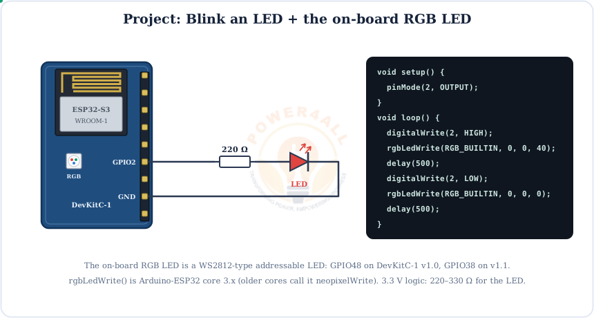
Project 1: Blink + RGB
void setup() { pinMode(2, OUTPUT); }
void loop() {
  digitalWrite(2, HIGH); rgbLedWrite(RGB_BUILTIN, 0, 0, 40); delay(500);
  digitalWrite(2, LOW);  rgbLedWrite(RGB_BUILTIN, 0, 0, 0);  delay(500);
}
Project 2: Wi-Fi web switch
/on or /off.#include <WiFi.h> #include <WebServer.h> WebServer server(80); void setup() { Serial.begin(115200); pinMode(2, OUTPUT); WiFi.begin("my-ssid", "password"); while (WiFi.status() != WL_CONNECTED) delay(300); Serial.println(WiFi.localIP()); server.on("/on", [](){ digitalWrite(2, HIGH); server.send(200, "text/plain", "LED ON"); }); server.on("/off", [](){ digitalWrite(2, LOW); server.send(200, "text/plain", "LED OFF"); }); server.begin(); } void loop() { server.handleClient(); }
Project 3: USB keyboard button (native USB)
#include "USB.h"
#include "USBHIDKeyboard.h"
USBHIDKeyboard Keyboard;
void setup() { pinMode(0, INPUT_PULLUP); Keyboard.begin(); USB.begin(); }
void loop() {
  if (digitalRead(0) == LOW) {
    Keyboard.println("Hello from ESP32-S3!");
    delay(500);                                   // simple debounce
  }
}
Project 4: Touch-to-wake battery gadget
void setup() {
  Serial.begin(115200); delay(500);
  Serial.println("Woke up!");
  rgbLedWrite(RGB_BUILTIN, 0, 40, 0); delay(1000);
  rgbLedWrite(RGB_BUILTIN, 0, 0, 0);
  touchSleepWakeUpEnable(T1, 40000);           // threshold: tune from touchRead()
  esp_deep_sleep_start();
}
void loop() {}
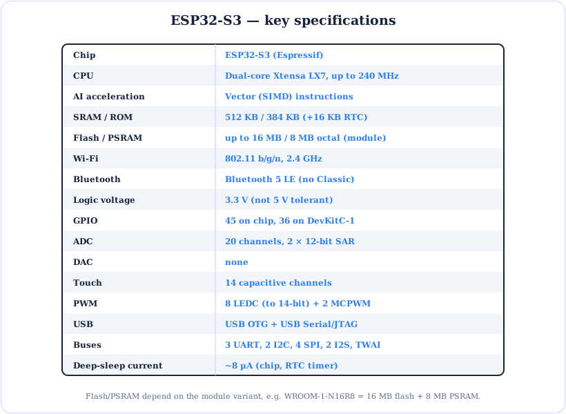
ESP32-S3 Specifications
The key numbers at a glance.
Key Terms — Glossary
| Term | Meaning |
|---|---|
| SoC | System-on-chip: CPU, memory, radio and peripherals on one die. |
| Xtensa LX7 | The 32-bit CPU core design used in the ESP32-S3 (two of them). |
| Vector / SIMD | Instructions that process several numbers at once, speeding up AI maths. |
| PSRAM | Extra RAM outside the chip; “octal” (OPI) uses 8 data lines for speed. |
| WROOM-1 | Espressif's certified module: chip + flash + PSRAM + antenna. |
| GPIO matrix | Internal switch that routes peripherals to almost any pin. |
| Strapping pin | A pin read at reset to choose the boot mode (GPIO0, 3, 45, 46). |
| USB OTG | USB that can act as a device or a host. |
| USB CDC | USB serial port class; how Serial works over native USB. |
| LEDC | The ESP32 PWM peripheral (“LED control”). |
| BLE 5 | Bluetooth Low Energy version 5: long range, 2 Mbps, mesh. |
| ULP | Ultra-low-power co-processor that runs while the main cores sleep. |
Frequently Asked Questions
Quick answers to the questions people ask most about the ESP32-S3.
What is the ESP32-S3?
A Wi-Fi and Bluetooth 5 LE microcontroller from Espressif with a dual-core Xtensa LX7 CPU at up to 240 MHz, vector instructions for AI, 512 KB SRAM, up to 16 MB flash and 8 MB PSRAM in its modules, 45 GPIO, a 12-bit ADC, 14 touch pins and native USB, all at 3.3 V logic.
What is the difference between the ESP32 and the ESP32-S3?
The S3 has newer LX7 cores with vector (AI) instructions, native USB OTG, more GPIO (45 vs 34), more touch pins (14 vs 10), octal PSRAM, camera and LCD interfaces and Bluetooth 5 LE. The original ESP32 keeps Bluetooth Classic and two 8-bit DACs, which the S3 lacks.
Does the ESP32-S3 have Bluetooth Classic?
No. It supports Bluetooth 5 Low Energy only (long range, 2 Mbps, mesh). BluetoothSerial and A2DP audio examples from the original ESP32 won't work; use BLE instead.
How many GPIO pins does the ESP32-S3 have?
45 programmable GPIO on the chip (GPIO0–21 and GPIO26–48). The DevKitC-1 exposes 36 of them on its two 22-pin headers; GPIO26–32 are used internally by the flash and PSRAM.
Is the ESP32-S3 5 V tolerant?
No. The GPIO work at 3.3 V and are not 5 V tolerant. Use a voltage divider or logic-level shifter for 5 V parts. The DevKitC-1 board itself can be powered with 5 V from USB-C or the 5V pin.
What does N16R8 mean on an ESP32-S3 module?
N16 = 16 MB of flash, R8 = 8 MB of octal PSRAM. N8R2 would be 8 MB flash and 2 MB quad PSRAM. With R8 modules choose OPI PSRAM in the Arduino IDE and avoid GPIO35–37.
Which ESP32-S3 pins should I avoid?
Avoid GPIO26–32 (flash/PSRAM) and, on octal-PSRAM R8 modules, GPIO35–37. Use GPIO0, 3, 45, 46 (strapping), 43/44 (UART0), 19/20 (USB) and 39–42 (JTAG) with care. Pins 1, 2, 4–18, 21, 38, 47 and 48 are generally safe.
Why does my ESP32-S3 not show up or fail to upload?
Use a data USB-C cable and select ESP32S3 Dev Module and the right port. If the native port isn't detected, hold BOOT, tap RST, release BOOT, upload, then press RST. For Serial output on the native port, set USB CDC On Boot = Enabled.
Conclusion & Key Takeaways
The ESP32-S3 is the go-to Espressif chip when a project needs more than Wi-Fi: AI, a camera, a display or USB. It also stays friendly to program in the Arduino IDE.
2 × LX7
240 MHz + vector AI.
N16R8
16 MB flash, 8 MB PSRAM.
Safe pins
1, 2, 4–18, 21, 38, 47, 48.
Native USB
CDC, HID, JTAG on 19/20.
BLE 5 only
No Bluetooth Classic.
3.3 V
Not 5 V tolerant.