ESP32-C3
Espressif's first RISC-V Wi-Fi chip. The ESP32-C3 combines a 160 MHz 32-bit RISC-V core with 2.4 GHz Wi-Fi, Bluetooth 5 LE and a built-in USB Serial/JTAG port — at ESP8266 prices. This guide covers the board anatomy, a complete GPIO map with every pin explained, strapping pins, ADC, PWM, buses, wireless, sleep modes, a family comparison, and ends with Arduino code and mini-projects.
Complete Learning Path — ESP32-C3
From the RISC-V chip and modules, to a full GPIO map with every pin detailed, USB Serial/JTAG, boot pins, power and sleep, ADC, PWM, buses, Wi-Fi, BLE 5, code examples and mini-projects
What is the ESP32-C3?
The ESP32-C3 is a low-cost Wi-Fi + Bluetooth 5 LE microcontroller (SoC) from Espressif. It is the first chip of the “C” series and the first Espressif chip built on the open RISC-V instruction set instead of Xtensa.
Think of it as the modern replacement for the ESP8266: similar price and size, but with Bluetooth LE, a faster 32-bit core, 400 KB of RAM, hardware security and a USB port that can program and debug the chip directly. It gives up a few things compared with the original ESP32 — one core instead of two, fewer GPIOs, no touch pins and no DAC — which keeps it small, cheap and efficient.
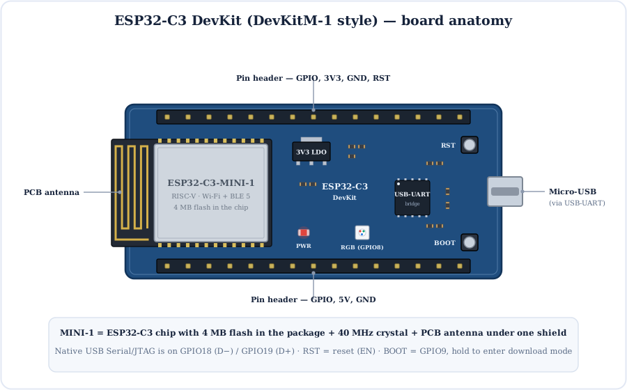
ESP32-C3 module
The metal can holds the chip, flash, a 40 MHz crystal and the PCB antenna (keep it clear of metal).
USB
DevKitM-style boards use a USB-UART bridge; tiny boards (XIAO, SuperMini) wire USB straight to the chip's USB Serial/JTAG.
3.3 V LDO
Drops 5 V from USB to the 3.3 V the chip needs. See our voltage regulator guide.
RST & BOOT
RST restarts the chip. BOOT pulls GPIO9 low so the chip waits for new firmware.
RGB LED
DevKitM-1 has an addressable RGB LED on GPIO8 — drive it with rgbLedWrite().
Pin headers
Expose the free GPIOs plus 3V3, 5V, GND and reset for breadboard use.
Inside the ESP32-C3: a RISC-V SoC
A RV32IMC RISC-V core at 160 MHz sits next to generous memory, a shared Wi-Fi/BLE radio, security hardware and a compact set of peripherals, all connected through a GPIO matrix.
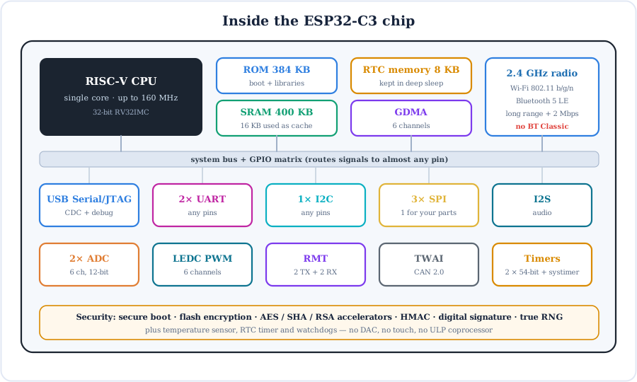
- RISC-V CPU — open instruction set (RV32IMC: integer, multiply/divide, compressed instructions). Your Arduino code runs unchanged; the compiler handles the difference.
- Memory — 400 KB SRAM (16 KB of it acts as flash cache), 384 KB ROM, and 8 KB RTC memory that survives deep sleep.
- Radio — one 2.4 GHz radio shared by Wi-Fi 802.11 b/g/n and Bluetooth 5 LE, which can run together.
- Security — secure boot, flash encryption, AES/SHA/RSA accelerators, HMAC and a digital-signature peripheral for safe cloud connections.
- What's missing — no touch sensor, no DAC and no ULP coprocessor. Keep that in mind when porting ESP32 projects.
ESP32-C3 Modules and Dev Boards
Espressif sells the chip in certified modules, and makers love tiny boards such as the Seeed XIAO ESP32C3 and the ESP32-C3 SuperMini.
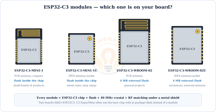
| Board / module | What it is | USB | Choose it for |
|---|---|---|---|
| ESP32-C3-DevKitM-1 | Espressif board with the MINI-1 module | USB-UART bridge | Learning, reference pinout |
| ESP32-C3-DevKitC-02 | Espressif board with WROOM-02 | USB-UART bridge | General prototyping |
| Seeed XIAO ESP32C3 | Thumb-sized board with battery charger | Native USB Serial/JTAG | Wearables, tiny sensors |
| ESP32-C3 SuperMini | Very low-cost mini board | Native USB Serial/JTAG | Cheap Wi-Fi/BLE nodes |
Tiny boards label their pins differently, but the GPIO numbers are the same chip pins — always use the GPIO map below.
Full ESP32-C3 GPIO Pinout
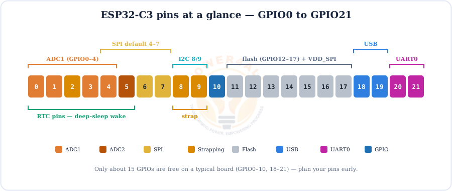
Every ESP32-C3 board exposes the same 22 chip GPIOs. This map shows each one with its ADC channel, JTAG, SPI, I2C, USB, UART, flash and strapping roles.
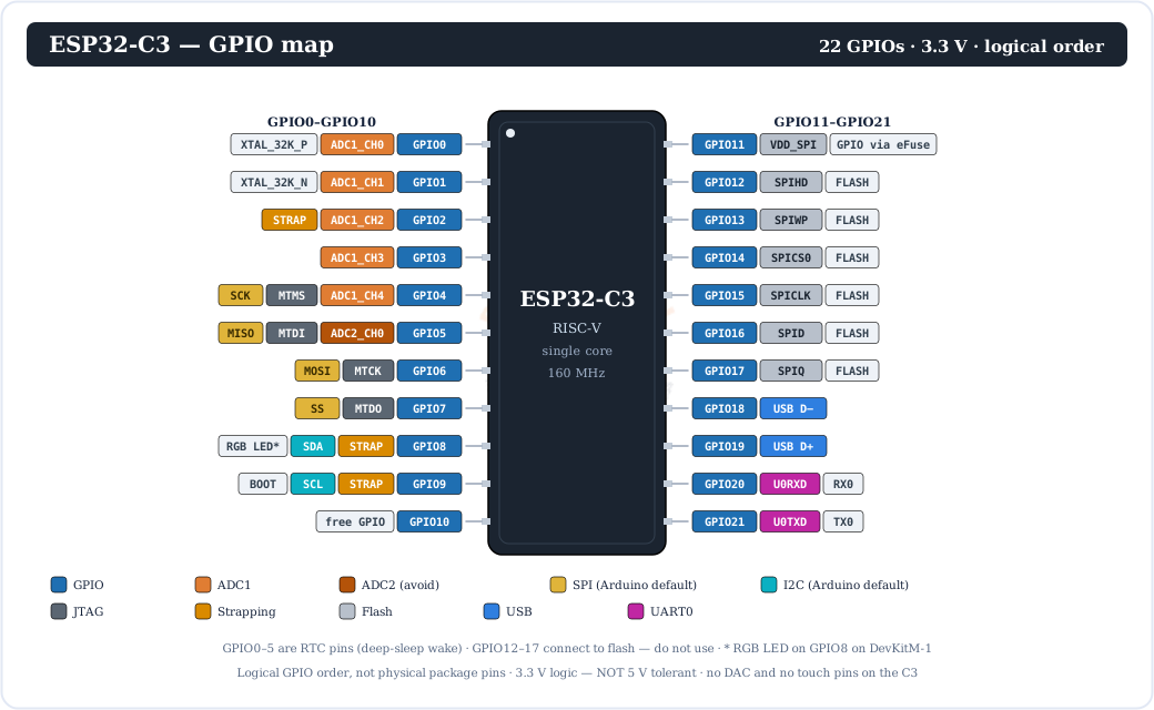
Here are the same pins as a quick colour-coded strip:
Every Pin Explained
With only 22 GPIOs, it pays to know exactly what each one does.
| GPIO | Main functions | Notes |
|---|---|---|
| GPIO0, 1 | ADC1_CH0/1, 32 kHz crystal, RTC | Free unless the board fits a 32.768 kHz crystal. Can wake from deep sleep. |
| GPIO2 | ADC1_CH2, strapping, RTC | Keep HIGH at reset; fine as an input or ADC afterwards. |
| GPIO3 | ADC1_CH3, RTC | Safest general-purpose / analog pin. |
| GPIO4 | ADC1_CH4, JTAG MTMS, SPI SCK, RTC | Arduino default SPI clock. |
| GPIO5 | ADC2_CH0, JTAG MTDI, SPI MISO, RTC | Use as digital; avoid ADC2 readings. |
| GPIO6, 7 | JTAG MTCK/MTDO, SPI MOSI/SS | Free GPIO when SPI and JTAG pins aren't needed. |
| GPIO8 | Strapping, I2C SDA (Arduino) | Must be HIGH for download mode; RGB LED on DevKitM-1. |
| GPIO9 | Strapping / BOOT, I2C SCL (Arduino) | LOW at reset = download mode. Has a pull-up and the BOOT button. |
| GPIO10 | General purpose | No special role — great for buttons and LEDs. |
| GPIO11 | VDD_SPI (flash power) | Only usable as GPIO after burning an eFuse — leave it alone. |
| GPIO12–17 | SPI flash (SPIHD, SPIWP, SPICS0, SPICLK, SPID, SPIQ) | Don't use. Wired to the flash memory. |
| GPIO18, 19 | USB D− / D+ | Used by USB Serial/JTAG; free only if you never use native USB. |
| GPIO20, 21 | UART0 RX / TX | Boot log and bridge-chip flashing on DevKit boards. |
Power & control pins (on dev boards)
- 5V — 5 V from USB, or a 5 V input into the on-board LDO.
- 3V3 — regulated 3.3 V for sensors (or a clean 3.3 V input if you skip USB).
- GND — ground.
- RST / EN — chip enable; pull LOW to reset.
3.3 V only: ESP32-C3 GPIOs are not 5 V tolerant. Use a resistor divider or level shifter for 5 V signals, and switch relays or motors with a transistor or logic-level MOSFET.
USB Serial/JTAG — Program and Debug with One Cable
The C3 has a built-in USB Serial/JTAG controller on GPIO18 (D−) and GPIO19 (D+). It appears on your PC as a serial port and a JTAG debugger — no CP2102 or CH340 required.
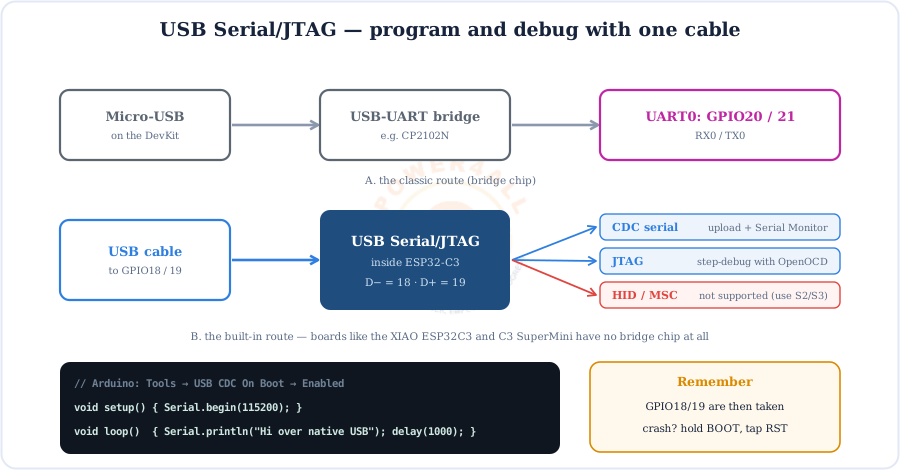
- Serial Monitor — in Arduino set Tools → USB CDC On Boot → Enabled so
Serialgoes over the native port. - Debugging — OpenOCD and the Arduino IDE 2 debugger can single-step code through the same cable.
- Not OTG — it cannot pretend to be a keyboard, mouse or flash drive. For that, choose the ESP32-S2 or ESP32-S3.
Strapping Pins and Boot Modes
At reset the ESP32-C3 reads GPIO2, GPIO8 and GPIO9 to decide how to start.
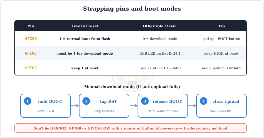
Common trap: Arduino's default I2C pins (SDA 8, SCL 9) are both strapping pins. That's fine because I2C pull-ups hold them HIGH — but never connect a sensor that pulls them LOW at power-up.
Powering the ESP32-C3
The chip needs 3.0–3.6 V. Dev boards take 5 V from USB or the 5V pin and drop it to 3.3 V with an LDO regulator.
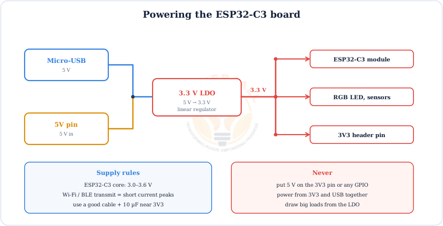
- Radio peaks — Wi-Fi transmit pulls short bursts of a few hundred mA; weak cables cause brown-out resets.
- Batteries — a Li-ion cell needs a low-dropout regulator or a buck/buck-boost converter for a steady 3.3 V. The XIAO ESP32C3 even has a charger built in.
- Decoupling — place 10 µF + 100 nF capacitors next to the 3V3 pin on custom boards.
Sleep Modes and Wake Sources
In deep sleep the C3 keeps only its RTC timer and 8 KB of RTC memory alive, drawing just a few microamps.
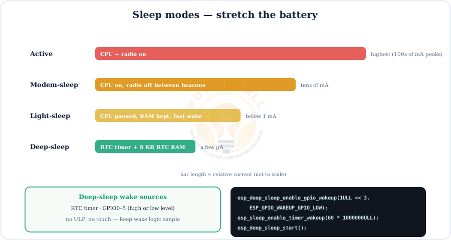
- Deep sleep restarts the program from
setup()on wake; save counters inRTC_DATA_ATTRvariables. - GPIO wake uses
esp_deep_sleep_enable_gpio_wakeup()and works on GPIO0–5 only. - Light sleep keeps RAM and wakes in microseconds — good for BLE devices that must answer quickly.
ADC — Analog Input
The ESP32-C3 has a 12-bit ADC (0–4095). Use the five ADC1 channels on GPIO0–4.
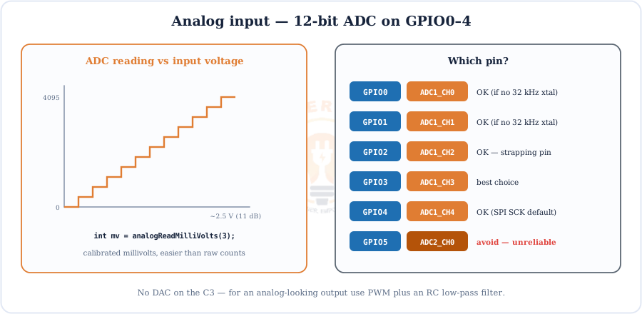
analogRead(pin)returns 0–4095;analogReadMilliVolts(pin)returns a calibrated voltage.- At maximum attenuation the useful range is about 0–2.5 V, not 3.3 V — use a resistor divider for higher voltages.
- No DAC on the C3: for an analog-style output use PWM with an RC low-pass filter.
PWM with the LEDC Controller
The LEDC peripheral gives 6 PWM channels that the GPIO matrix can route to almost any output pin.
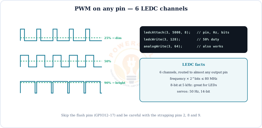
ledcAttach(pin, freq, bits)thenledcWrite(pin, duty)(Arduino-ESP32 3.x);analogWrite()also works.- frequency × 2bits must stay below the 80 MHz clock — e.g. 5 kHz at 8-bit, or 20 kHz at 10-bit.
UART, I2C, SPI, I2S, TWAI & RMT
The C3 has a compact but complete set of buses, and the GPIO matrix lets you move most of them.
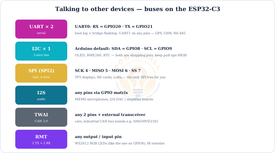
begin(pins).Tip: the C3 has only one I2C controller, but many sensors can share it by address. Size the pull-ups with our pull-up resistor calculator.
Wi-Fi on the ESP32-C3
The C3 speaks 2.4 GHz 802.11 b/g/n as a station, an access point, or both, using the same WiFi.h library as every ESP32.
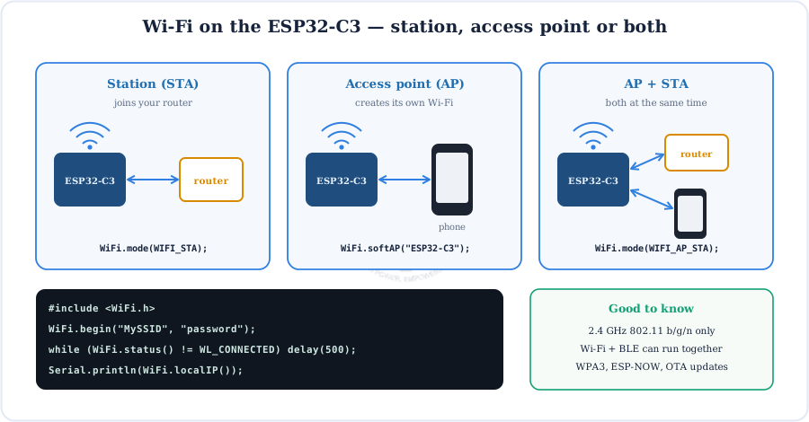
Supports WPA3, ESP-NOW, OTA updates, mDNS, WebServer, HTTPClient and TLS — and it is a favourite chip for ESPHome and Home Assistant devices.
Bluetooth 5 LE
The C3 supports Bluetooth 5 Low Energy, so it can talk straight to phones, beacons and BLE sensors.
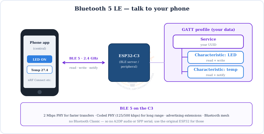
- BLE 5 features — 2 Mbps PHY, Coded PHY long range, advertising extensions and mesh.
- Libraries — the built-in
BLEDevicelibrary or the lighterNimBLE-Arduino. - No Bluetooth Classic — for audio (A2DP) or SPP serial, use the original ESP32.
Programming the ESP32-C3
Use the Arduino IDE, Espressif's ESP-IDF, MicroPython, ESPHome or Rust.
- Arduino IDE → Boards Manager → install esp32 by Espressif Systems.
- Select ESP32C3 Dev Module (or your board, e.g. XIAO_ESP32C3) and the port.
- Board without a bridge chip? Set USB CDC On Boot → Enabled.
- Click Upload. If nothing happens: hold BOOT, tap RST, release BOOT, upload, then press RST.
Port disappears? With native USB the port can vanish if the sketch crashes or sleeps. The BOOT + RST sequence always brings the chip back into download mode.
Code Examples
Short, copy-paste Arduino sketches for the main ESP32-C3 features.
1. Blink an LED on GPIO3
const int LED = 3;                     // LED + 220 Ω to GND
void setup() { pinMode(LED, OUTPUT); }
void loop() {
  digitalWrite(LED, HIGH); delay(500);
  digitalWrite(LED, LOW);  delay(500);
}
2. Cycle the on-board RGB LED (GPIO8)
void setup() {}
void loop() {
  rgbLedWrite(8, 64, 0, 0);  delay(500);   // red   (Arduino-ESP32 3.x)
  rgbLedWrite(8, 0, 64, 0);  delay(500);   // green
  rgbLedWrite(8, 0, 0, 64);  delay(500);   // blue
}
3. Scan for Wi-Fi networks
#include <WiFi.h>
void setup() { Serial.begin(115200); WiFi.mode(WIFI_STA); }
void loop() {
  int n = WiFi.scanNetworks();
  for (int i = 0; i < n; i++)
    Serial.printf("%-24s %4d dBm\n", WiFi.SSID(i).c_str(), WiFi.RSSI(i));
  Serial.println();
  delay(5000);
}
4. Read the ADC in millivolts
void setup() { Serial.begin(115200); }
void loop() {
  int raw = analogRead(1);            // GPIO1 = ADC1_CH1, 0..4095
  int mv  = analogReadMilliVolts(1);  // calibrated
  Serial.printf("raw=%d  %d mV\n", raw, mv);
  delay(200);
}
5. Deep sleep, wake on a button (GPIO3)
RTC_DATA_ATTR int wakes = 0;          // kept in RTC memory
void setup() {
  Serial.begin(115200);
  delay(1000);
  Serial.printf("Wake number %d\n", ++wakes);
  pinMode(3, INPUT_PULLUP);             // button GPIO3 to GND
  esp_deep_sleep_enable_gpio_wakeup(1ULL << 3, ESP_GPIO_WAKEUP_GPIO_LOW);
  esp_deep_sleep_start();
}
void loop() {}
Beginner Mini-Projects
Four small builds that use the C3's strengths: Wi-Fi, BLE and low power.
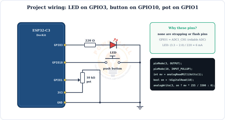
Project 1 — Knob-controlled dimmer
bool lampOn = true, lastBtn = HIGH;

void setup() {
  pinMode(10, INPUT_PULLUP);
  ledcAttach(3, 5000, 8);               // 5 kHz, 8-bit PWM on GPIO3
}
void loop() {
  bool btn = digitalRead(10);
  if (lastBtn == HIGH && btn == LOW) lampOn = !lampOn;   // toggle on press
  lastBtn = btn;
  int mv = analogReadMilliVolts(1);       // ~0..2500 mV
  int duty = constrain(mv * 255 / 2500, 0, 255);
  ledcWrite(3, lampOn ? duty : 0);
  delay(20);
}
Project 2 — Wi-Fi web-controlled LED
#include <WiFi.h>
#include <WebServer.h>
WebServer server(80);

void setup() {
  Serial.begin(115200);
  pinMode(3, OUTPUT);
  WiFi.begin("MySSID", "password");
  while (WiFi.status() != WL_CONNECTED) delay(500);
  server.on("/",    []() { server.send(200, "text/html", "<a href='/on'>ON</a> | <a href='/off'>OFF</a>"); });
  server.on("/on",  []() { digitalWrite(3, HIGH); server.send(200, "text/plain", "LED ON"); });
  server.on("/off", []() { digitalWrite(3, LOW);  server.send(200, "text/plain", "LED OFF"); });
  server.begin();
  Serial.println(WiFi.localIP());
}
void loop() { server.handleClient(); }
Project 3 — BLE switch from your phone
#include <BLEDevice.h>
#include <BLEServer.h>

class LedCallback : public BLECharacteristicCallbacks {
  void onWrite(BLECharacteristic *c) {
    String v = c->getValue();             // Arduino-ESP32 3.x returns String
    if (v.length()) digitalWrite(3, v[0] == '1' ? HIGH : LOW);
  }
};

void setup() {
  pinMode(3, OUTPUT);
  BLEDevice::init("ESP32-C3 LED");
  BLEServer *server = BLEDevice::createServer();
  BLEService *svc = server->createService("19B10000-E8F2-537E-4F6C-D104768A1214");
  BLECharacteristic *ch = svc->createCharacteristic("19B10001-E8F2-537E-4F6C-D104768A1214",
      BLECharacteristic::PROPERTY_READ | BLECharacteristic::PROPERTY_WRITE);
  ch->setCallbacks(new LedCallback());
  svc->start();
  BLEDevice::getAdvertising()->addServiceUUID("19B10000-E8F2-537E-4F6C-D104768A1214");
  BLEDevice::startAdvertising();
}
void loop() { delay(1000); }
Project 4 — Battery sensor that sleeps
RTC_DATA_ATTR int readings = 0;

void setup() {
  Serial.begin(115200);
  delay(1000);
  int mv = analogReadMilliVolts(1);     // GPIO1 = ADC1_CH1
  Serial.printf("Reading %d: %d mV\n", ++readings, mv);
  esp_sleep_enable_timer_wakeup(30ULL * 1000000);
  esp_deep_sleep_start();               // a few µA until the next wake
}
void loop() {}
ESP32-C3 vs ESP32 vs ESP32-S2 vs ESP32-S3
All four chips do 2.4 GHz Wi-Fi at 3.3 V; they differ in core, Bluetooth, USB and pin count.
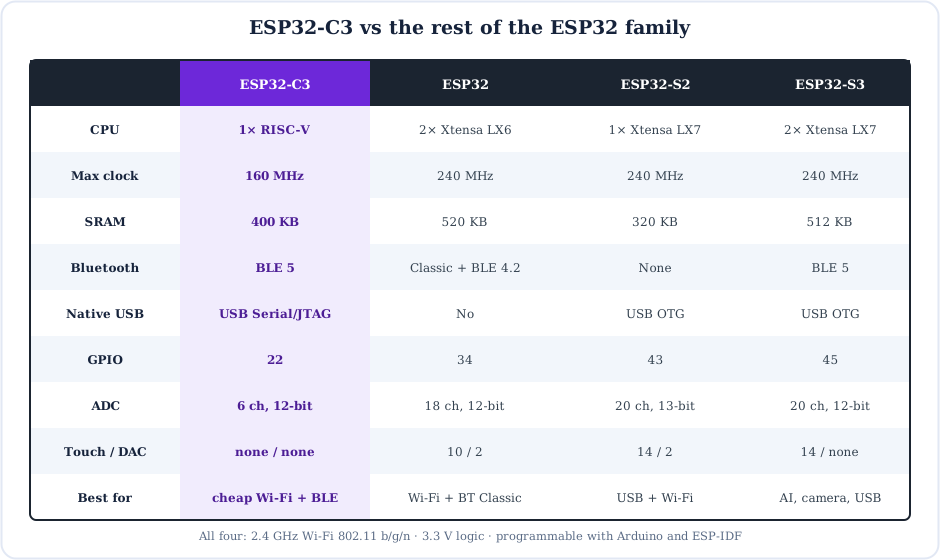
- Pick the ESP32-C3 for the cheapest Wi-Fi + BLE 5 node, ESPHome devices and ESP8266 upgrades.
- Pick the original ESP32 for two cores, touch, DAC or Bluetooth Classic audio.
- Pick the ESP32-S2 for USB HID/MSC gadgets when Bluetooth isn't needed.
- Pick the ESP32-S3 for cameras, AI/vector maths, USB OTG and BLE 5 together.
Specifications
The ESP32-C3 at a glance.
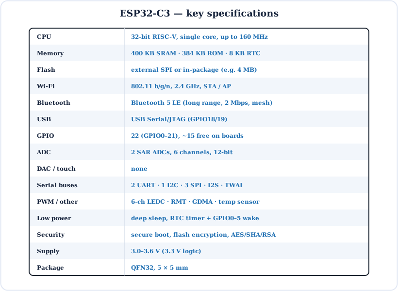
| Parameter | Value |
|---|---|
| CPU | 32-bit RISC-V (RV32IMC), single core, up to 160 MHz |
| On-chip memory | 400 KB SRAM (16 KB cache), 384 KB ROM, 8 KB RTC SRAM |
| Flash | External SPI flash or in-package (e.g. 4 MB) |
| Wi-Fi | 802.11 b/g/n, 2.4 GHz, station / soft-AP |
| Bluetooth | Bluetooth 5 LE (2 Mbps, Coded PHY long range, mesh) |
| USB | USB Serial/JTAG controller (GPIO18 D−, GPIO19 D+) |
| GPIO | 22 (GPIO0–21), about 15 free on typical boards |
| ADC | 2 × 12-bit SAR ADC, 6 channels (ADC1 GPIO0–4) |
| DAC / touch | None |
| Interfaces | 2 × UART, 1 × I2C, 3 × SPI, I2S, TWAI (CAN), LEDC (6 ch), RMT, GDMA |
| Low power | Light sleep, deep sleep; wake by timer or GPIO0–5 |
| Security | Secure boot, flash encryption, AES / SHA / RSA, HMAC, digital signature |
| Supply voltage | 3.0–3.6 V (3.3 V logic, not 5 V tolerant) |
| Package | QFN32, 5 × 5 mm |
Key Terms — Glossary
| Term | Meaning |
|---|---|
| RISC-V | An open, royalty-free CPU instruction set; the C3 uses the 32-bit RV32IMC variant. |
| SoC | System-on-chip: CPU, memory, radio and peripherals on one piece of silicon. |
| BLE 5 | Bluetooth Low Energy version 5 — faster (2 Mbps) and longer range (Coded PHY) than BLE 4.2. |
| GATT | How BLE data is organised: services containing characteristics. |
| USB Serial/JTAG | The C3's built-in USB block: a serial port plus a JTAG debugger. |
| Strapping pin | A pin read once at reset to choose the boot mode (GPIO2, 8, 9 on the C3). |
| GPIO matrix | Internal switchboard that routes peripheral signals to almost any pin. |
| eFuse | One-time programmable bits that store settings and keys inside the chip. |
| RTC domain | The always-on part of the chip (timer, RTC memory, GPIO0–5 wake). |
| LEDC | The LED-control PWM peripheral (6 channels on the C3). |
| RMT | Remote-control peripheral for precise pulse trains (WS2812 LEDs, IR). |
| TWAI | Espressif's CAN 2.0 controller (Two-Wire Automotive Interface). |
Frequently Asked Questions
Quick answers to the questions people ask most about the ESP32-C3.
What is the ESP32-C3?
A low-cost Wi-Fi and Bluetooth 5 LE system-on-chip from Espressif built around a single-core 32-bit RISC-V CPU at up to 160 MHz, with 400 KB SRAM, 22 GPIOs, a 12-bit ADC and a built-in USB Serial/JTAG port. It is popular for smart-home devices, sensors and as a modern ESP8266 replacement.
Does the ESP32-C3 have Bluetooth?
Yes — Bluetooth 5 Low Energy with 2 Mbps PHY, Coded PHY long range, advertising extensions and mesh. It does not support Bluetooth Classic, so A2DP audio and SPP serial need the original ESP32.
What is the difference between the ESP32 and the ESP32-C3?
The ESP32 has two Xtensa LX6 cores at 240 MHz, 520 KB SRAM, Bluetooth Classic + BLE 4.2, 34 GPIOs, touch pins and a DAC. The ESP32-C3 has one RISC-V core at 160 MHz, 400 KB SRAM, BLE 5 only, 22 GPIOs, no touch or DAC, but adds USB Serial/JTAG, better security and a lower price.
How many GPIO pins does the ESP32-C3 have?
22 GPIOs, GPIO0–21. GPIO12–17 normally connect to the SPI flash and GPIO11 powers it, so about 15 pins (GPIO0–10 and 18–21) are free. GPIO18/19 are the USB pins and GPIO20/21 are UART0.
Which pins are the ESP32-C3 strapping pins?
GPIO2, GPIO8 and GPIO9. GPIO9 HIGH at reset boots from flash; GPIO9 LOW with GPIO8 HIGH enters download mode; GPIO2 should also be HIGH. The BOOT button is on GPIO9 and many boards have an RGB LED on GPIO8, so avoid pulling these pins low at power-up.
Does the ESP32-C3 have native USB?
It has a built-in USB Serial/JTAG controller on GPIO18 (D−) and GPIO19 (D+) that gives a CDC serial port for uploading and the Serial Monitor plus JTAG debugging, with no bridge chip. It is not a full USB OTG controller, so it cannot act as a keyboard, mouse or flash drive.
Which ADC pins should I use on the ESP32-C3?
Use ADC1 on GPIO0–4. The ADC is 12-bit (0–4095) with about 0–2.5 V range at the highest attenuation. ADC2 on GPIO5 is not recommended because Espressif reports it can give unreliable readings.
How do I program the ESP32-C3 with the Arduino IDE?
Install the esp32 by Espressif Systems package, select ESP32C3 Dev Module or your board, choose the port and click Upload. On boards without a USB bridge set USB CDC On Boot to Enabled to see Serial output. If the board isn't detected, hold BOOT, tap RST, release BOOT and upload again.
Is the ESP32-C3 better than the ESP8266?
For new designs, usually yes. It costs about the same but adds Bluetooth 5 LE, a faster 160 MHz 32-bit RISC-V core, far more RAM, hardware security, more GPIOs and a better ADC, while keeping low power consumption and Arduino compatibility.
Is the ESP32-C3 5 V tolerant?
No. It runs on 3.0–3.6 V and its GPIOs are not 5 V tolerant. Use a resistor divider or level shifter for 5 V signals, and power dev boards from USB or the 5V pin, which feed the on-board 3.3 V regulator.
Conclusion & Key Takeaways
The ESP32-C3 packs Wi-Fi, Bluetooth 5 LE, a modern RISC-V core and USB debugging into a tiny, cheap chip — the natural choice for connected sensors, smart-home gadgets and anyone upgrading from the ESP8266.
RISC-V @ 160 MHz
Single core, 400 KB SRAM.
Wi-Fi + BLE 5
No Bluetooth Classic.
USB Serial/JTAG
GPIO18/19, no bridge chip.
22 GPIOs
Avoid 11–17; straps 2/8/9.
12-bit ADC
Use ADC1 on GPIO0–4.
Low power
Deep sleep, wake on GPIO0–5.