ESP32-S2
Espressif's Wi-Fi chip with native USB. The ESP32-S2 puts a single-core Xtensa LX7 at 240 MHz, 43 GPIOs, a 13-bit ADC, DACs, touch pads and a USB OTG port on one low-power chip. This guide covers the board anatomy, a complete GPIO map with every pin explained, strapping pins, sleep modes, analog and buses, a family comparison, and finishes with Arduino code and mini-projects.
Complete Learning Path — ESP32-S2
From the chip and modules, to a full GPIO map with every pin detailed, native USB, boot pins, power and sleep, analog, touch, PWM, buses, Wi-Fi, code examples and mini-projects
What is the ESP32-S2?
The ESP32-S2 is a Wi-Fi microcontroller (SoC) from Espressif. It is the first chip of the ESP32 “S” series and was designed to be cheaper, lower-power and more secure than the original ESP32, with one headline feature the ESP32 never had: native USB.
To get there Espressif made some trade-offs. The S2 has one CPU core instead of two and no Bluetooth, but it adds more GPIOs (43), a 13-bit ADC, 14 touch pads, a RISC-V ultra-low-power coprocessor and hardware security. That makes it a great fit for Wi-Fi sensors, USB gadgets (keyboards, MIDI controllers, flash drives) and battery-powered IoT devices.
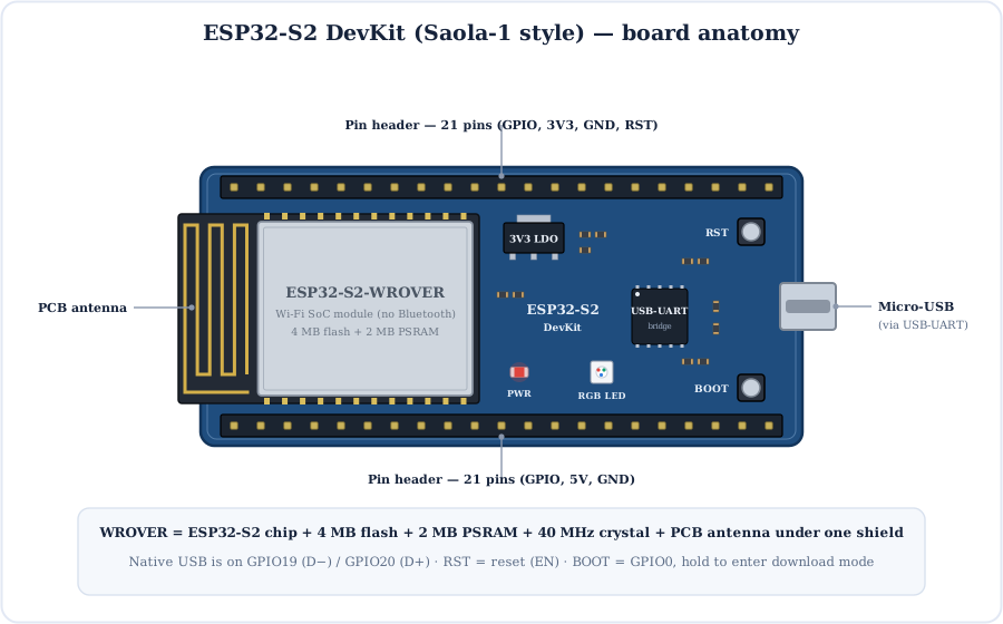
ESP32-S2 module
The metal can holds the ESP32-S2 chip, SPI flash (and PSRAM on WROVER), a 40 MHz crystal and the PCB antenna.
Micro-USB + bridge
On Saola-style boards a USB-UART chip links the micro-USB to UART0 (GPIO43/44) for flashing and the Serial Monitor.
3.3 V LDO
Turns 5 V from USB or the 5V pin into the 3.3 V the chip needs. See our voltage regulator guide.
RST & BOOT
RST restarts the chip. BOOT pulls GPIO0 low so the chip waits for new firmware.
RGB LED
Many S2 boards carry an addressable RGB LED (on Saola-1 it is on GPIO18) for status colours.
Pin headers
Two 21-pin rows expose the GPIOs, 3V3, 5V, GND and reset for breadboard use.
Inside the ESP32-S2 Chip
One chip, a whole system: a 240 MHz LX7 CPU, memory, a Wi-Fi radio, security hardware and a long list of peripherals, all joined by a GPIO matrix that can send most signals to almost any pin.
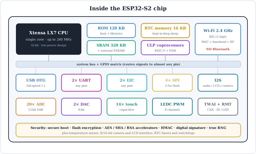
- CPU — one 32-bit Xtensa LX7 core up to 240 MHz. Fast enough for Wi-Fi, web servers, displays and audio.
- Memory — 320 KB SRAM and 128 KB ROM on chip, plus external SPI flash for your program and optional PSRAM (2 MB on WROVER) for big buffers.
- RTC memory (16 KB) — stays powered in deep sleep, so variables marked
RTC_DATA_ATTRsurvive a sleep cycle. - ULP coprocessors — a tiny RISC-V core and an FSM that can read sensors while the main CPU sleeps.
- Security — secure boot, flash encryption, AES/SHA/RSA accelerators, HMAC and a digital-signature peripheral protect your firmware and cloud keys.
ESP32-S2 Modules and Dev Boards
You rarely solder the bare chip. Espressif sells it in certified modules, and dev boards like the Saola-1, DevKitM-1 or the popular S2 Mini put a module on a breadboard-friendly PCB.
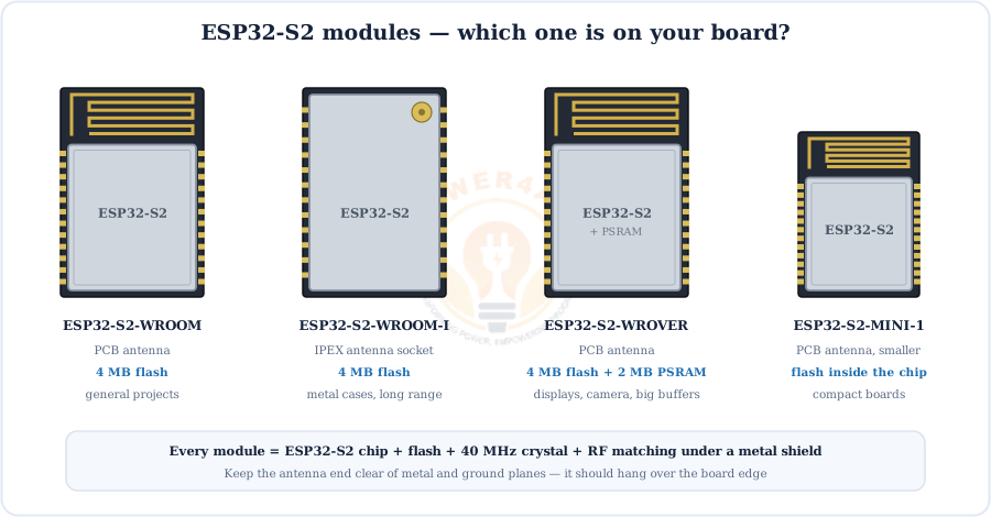
| Module | Antenna | Memory | Choose it for |
|---|---|---|---|
| ESP32-S2-WROOM | PCB | 4 MB flash | General Wi-Fi projects |
| ESP32-S2-WROOM-I | IPEX socket (external) | 4 MB flash | Metal enclosures, longer range |
| ESP32-S2-WROVER | PCB | 4 MB flash + 2 MB PSRAM | Displays, cameras, big JSON / audio buffers |
| ESP32-S2-MINI-1 | PCB | Flash inside the chip package | Small boards and products |
Full ESP32-S2 GPIO Pinout
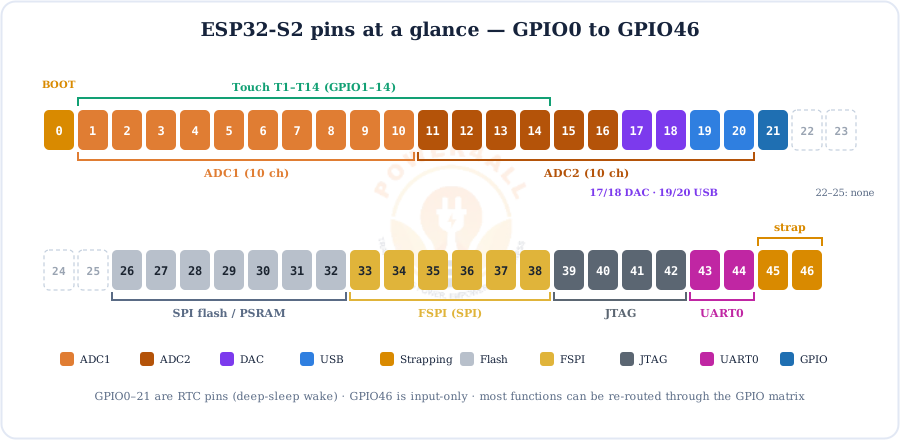
Dev boards arrange their headers differently, but the GPIO numbers and functions are fixed by the chip. This map shows all 43 GPIOs with their ADC channel, touch pad, DAC, USB, SPI, UART, JTAG, flash and strapping roles — use it with any ESP32-S2 board.
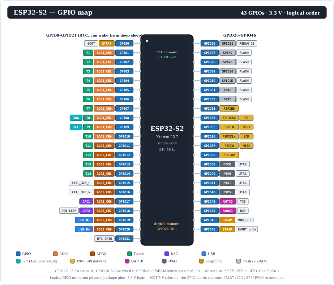
For a quick overview, here are all pin numbers colour-coded by their main job:
Every Pin Explained
Let's go through each group of pins, what it can do, and which ones to avoid.
| GPIO | Main functions | Notes |
|---|---|---|
| GPIO0 | Strapping (boot mode), RTC GPIO | BOOT button. Keep it HIGH at reset for normal start-up. |
| GPIO1–10 | ADC1_CH0–9, touch T1–T10 | Best analog pins — ADC1 works while Wi-Fi is on. GPIO8/9 are the default I2C SDA/SCL in Arduino. |
| GPIO11–14 | ADC2_CH0–3, touch T11–T14 | ADC2 is shared with Wi-Fi — digital use is fine. |
| GPIO15, 16 | ADC2_CH4/5, 32 kHz crystal | Free unless your board fits an external 32.768 kHz crystal. |
| GPIO17, 18 | ADC2_CH6/7, DAC1 / DAC2 | True 8-bit analog outputs. GPIO18 drives the RGB LED on Saola-1. |
| GPIO19, 20 | ADC2_CH8/9, USB D− / D+ | Taken when you use native USB. |
| GPIO21 | RTC GPIO | General purpose, can wake from deep sleep. |
| GPIO22–25 | — | Do not exist on the ESP32-S2. |
| GPIO26–32 | SPI flash / PSRAM (SPICS1, SPIHD, SPIWP, SPICS0, SPICLK, SPIQ, SPID) | Don't use. Wired to the module's memory; GPIO26 is the PSRAM chip-select on WROVER. |
| GPIO33–38 | FSPI (SPI2): 34 = SS, 35 = MOSI, 36 = SCK, 37 = MISO | Arduino default SPI pins; free GPIO otherwise. |
| GPIO39–42 | JTAG: MTCK, MTDO, MTDI, MTMS | Usable as GPIO unless you debug with JTAG. |
| GPIO43, 44 | UART0 TX / RX | Boot log and USB-UART flashing on bridge boards. |
| GPIO45 | Strapping (VDD_SPI voltage) | Leave LOW at reset (3.3 V flash). |
| GPIO46 | Strapping, input-only | No output, no pull-up; keep LOW at reset. |
Power & control pins (on dev boards)
- 5V — 5 V from USB, or a 5 V input into the on-board LDO.
- 3V3 — the regulated 3.3 V rail for sensors (or a clean 3.3 V input if you skip USB).
- GND — ground; several pins on both headers.
- RST / EN — chip enable; pull LOW to reset.
3.3 V only: ESP32-S2 GPIOs are not 5 V tolerant. Use a resistor divider for 5 V outputs coming in and a level shifter for two-way signals. For relays and motors, switch them with a transistor or logic-level MOSFET.
Native USB OTG — the S2 Superpower
The ESP32-S2 has a full-speed USB OTG controller built in, on GPIO19 (D−) and GPIO20 (D+). With the TinyUSB stack your board can plug into a PC and appear as a keyboard, mouse, serial port, flash drive or MIDI instrument.
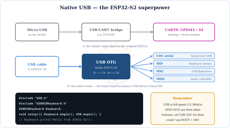
- CDC (serial) —
Serialover native USB, no bridge chip needed (Arduino: Tools → USB CDC On Boot → Enabled). - HID —
USBHIDKeyboardandUSBHIDMousefor macro pads, password typers and game controllers. - MSC — expose flash or an SD card as a USB drive (CircuitPython uses this to show a
CIRCUITPYdrive). - Firmware upload — boards without a bridge chip (such as the S2 Mini) are flashed straight over native USB.
Strapping Pins and Boot Modes
At the moment of reset the ESP32-S2 reads three strapping pins — GPIO0, GPIO45 and GPIO46 — to decide how to start.
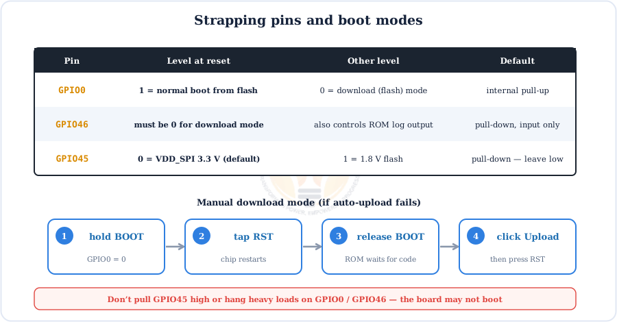
Rule of thumb: don't connect anything to GPIO0, GPIO45 or GPIO46 that could pull them the wrong way during reset (for example a sensor output, a pull-up on GPIO45, or a large capacitor on GPIO0).
Powering the ESP32-S2
The chip needs 3.0–3.6 V. Dev boards take 5 V from USB or the 5V pin and drop it to 3.3 V with an LDO regulator.
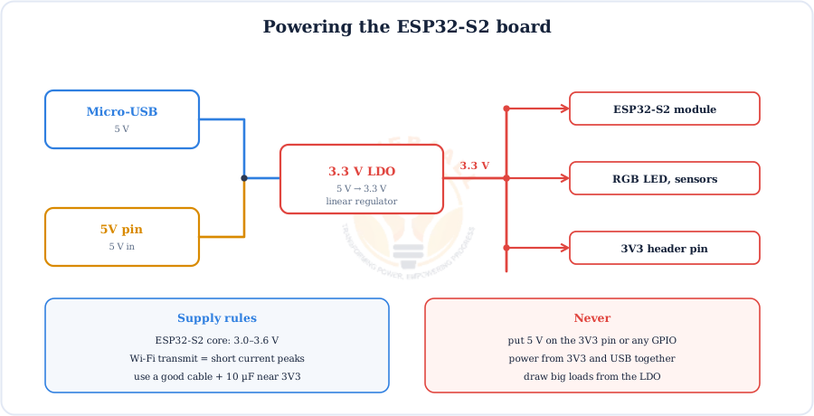
- Wi-Fi peaks — the radio pulls short bursts of a few hundred mA. Weak cables or long wires cause brown-out resets.
- Batteries — a single Li-ion cell (3.0–4.2 V) needs a low-dropout regulator or a buck/buck-boost converter to give a steady 3.3 V.
- Decoupling — add a 10 µF + 100 nF capacitor pair close to the 3V3 pin on custom boards.
Sleep Modes and the ULP Coprocessor
Low power is one of the ESP32-S2's design goals. Switching off what you don't need can stretch battery life from hours to months.
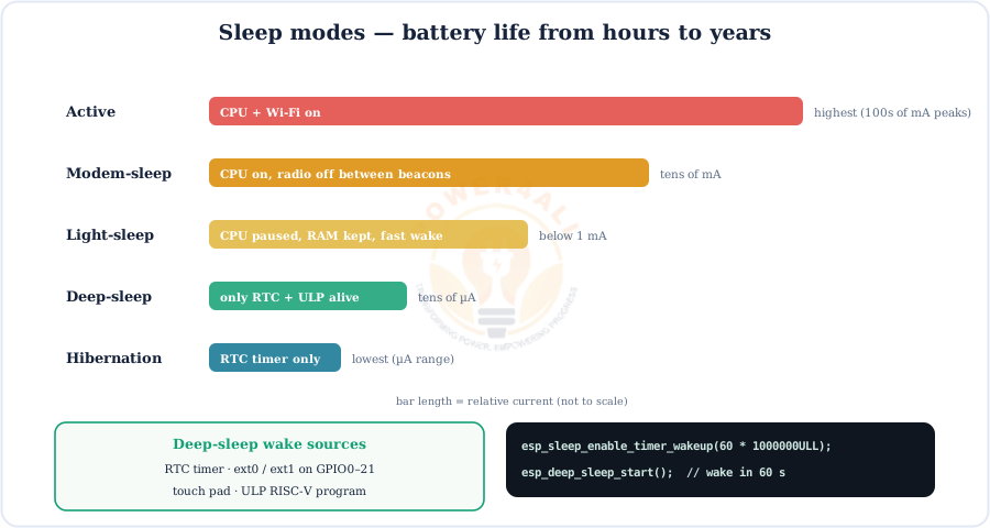
- Deep sleep keeps only the RTC domain alive; the chip restarts from
setup()on wake. Save state inRTC_DATA_ATTRvariables. - Wake sources — timer, a level on an RTC GPIO (GPIO0–21), a touch pad or a ULP program.
- ULP RISC-V — can sample a sensor every few seconds and only wake the main CPU when a threshold is crossed.
ADC and DAC
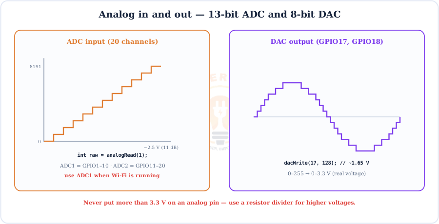
The ESP32-S2 has 20 ADC channels with a 13-bit result (0–8191) and two 8-bit DACs for real analog output.
| Feature | Pins | Arduino | Tip |
|---|---|---|---|
| ADC1 | GPIO1–10 | analogRead(pin), analogReadMilliVolts(pin) | Works with Wi-Fi on — use these first. |
| ADC2 | GPIO11–20 | analogRead(pin) | Shared with the Wi-Fi driver; readings can fail while Wi-Fi runs. |
| Attenuation | all ADC pins | analogSetAttenuation() | Max attenuation (11 dB) gives about 0–2.5 V full scale. |
| DAC | GPIO17, GPIO18 | dacWrite(pin, 0–255) | Audio tones, bias voltages, simple waveforms. |
Need to measure more than 2.5 V? Use a resistor divider — our resistor guide explains the maths — and analogReadMilliVolts() for a calibrated reading.
Capacitive Touch Pins
14 touch pads (T1–T14 on GPIO1–14) sense a finger through plastic or glass — no mechanical button needed.
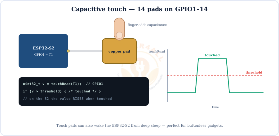
touchRead() value goes up when touched (the original ESP32 goes down).Read a baseline at start-up and compare against it, because the raw value depends on pad size and wire length. Touch pads can also wake the chip from deep sleep.
PWM with the LEDC Controller
The LEDC peripheral provides 8 PWM channels that the GPIO matrix can route to almost any output pin.
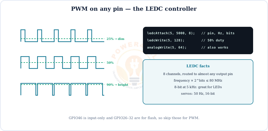
ledcAttach(pin, freq, bits)thenledcWrite(pin, duty)(Arduino-ESP32 3.x).analogWrite()also works.- Higher frequency means lower resolution: frequency × 2bits must stay under the 80 MHz clock.
- Typical settings: LEDs 5 kHz / 8-bit, servos 50 Hz / 14–16-bit, motors 20 kHz / 10-bit.
UART, I2C, SPI, I2S, TWAI & RMT
Thanks to the GPIO matrix you can put most buses on the pins that suit your layout. These are the defaults the Arduino core uses.
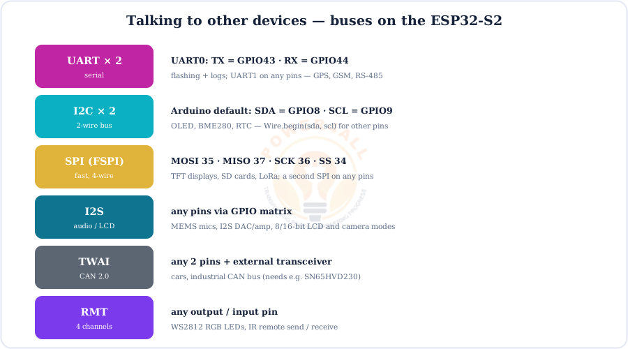
Tip: I2C needs pull-up resistors (most sensor breakouts include them). For long wires or many devices, size them with our pull-up resistor calculator.
Wi-Fi on the ESP32-S2
The S2 speaks 2.4 GHz 802.11 b/g/n. It can join your router (station), create its own network (access point), or do both — but it has no Bluetooth.
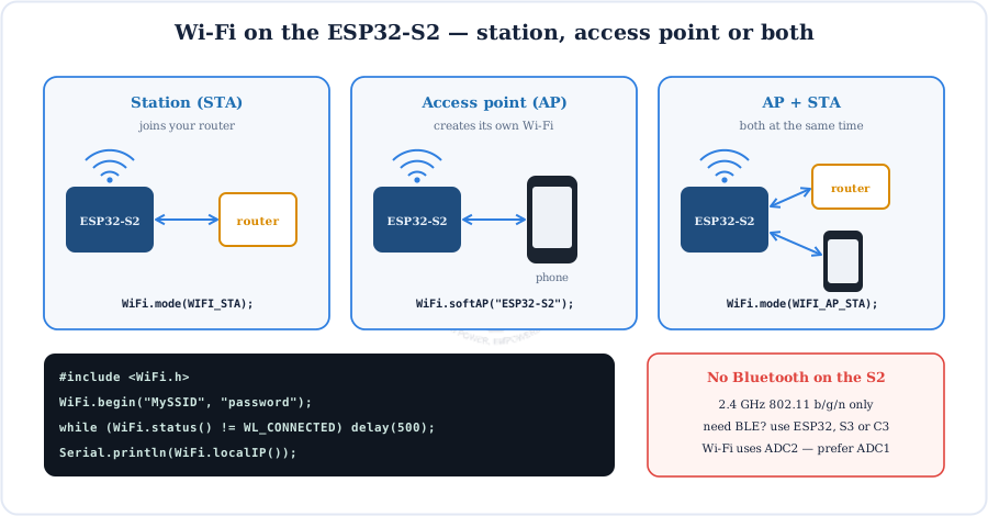
WiFi.h library as the original ESP32.All the usual ESP32 networking libraries work: WebServer, HTTPClient, WiFiClientSecure (TLS), MQTT clients, OTA updates, ESP-NOW and mDNS.
Programming the ESP32-S2
The S2 works with the Arduino IDE, Espressif's ESP-IDF, MicroPython and CircuitPython.
- Arduino IDE → Boards Manager → install esp32 by Espressif Systems.
- Select ESP32S2 Dev Module (or your board, e.g. LOLIN S2 Mini) and the port.
- Using native USB for serial? Set USB CDC On Boot → Enabled.
- Click Upload. If nothing happens: hold BOOT, tap RST, release BOOT, upload, then press RST to run.
Port disappears after upload? With native USB the COM port belongs to your sketch. A crash or deep sleep removes it — use the BOOT + RST sequence to get it back.
Code Examples
Short, copy-paste Arduino sketches for the main ESP32-S2 features.
1. Blink an LED on GPIO5
const int LED = 5;                     // LED + 220 Ω to GND
void setup() { pinMode(LED, OUTPUT); }
void loop() {
  digitalWrite(LED, HIGH); delay(500);
  digitalWrite(LED, LOW);  delay(500);
}
2. Scan for Wi-Fi networks
#include <WiFi.h>
void setup() {
  Serial.begin(115200);
  WiFi.mode(WIFI_STA);
}
void loop() {
  int n = WiFi.scanNetworks();
  for (int i = 0; i < n; i++)
    Serial.printf("%-24s %4d dBm\n", WiFi.SSID(i).c_str(), WiFi.RSSI(i));
  Serial.println();
  delay(5000);
}
3. Read a touch pad
void setup() { Serial.begin(115200); }
void loop() {
  Serial.println(touchRead(T1));      // GPIO1 — value rises when touched
  delay(100);
}
4. ADC in, DAC out
void setup() { Serial.begin(115200); }
void loop() {
  int raw = analogRead(1);           // GPIO1 = ADC1_CH0, 0..8191
  int mv  = analogReadMilliVolts(1);  // calibrated millivolts
  Serial.printf("raw=%d  %d mV\n", raw, mv);
  dacWrite(17, raw >> 5);            // 13-bit -> 8-bit, out on GPIO17
  delay(200);
}
5. Deep sleep with a boot counter
RTC_DATA_ATTR int boots = 0;          // kept in RTC memory
void setup() {
  Serial.begin(115200);
  delay(1000);
  boots++;
  Serial.printf("Boot number %d\n", boots);
  esp_sleep_enable_timer_wakeup(10ULL * 1000000);  // 10 s
  esp_deep_sleep_start();
}
void loop() {}
Beginner Mini-Projects
Four small builds that show off what makes the ESP32-S2 different: touch, Wi-Fi and native USB.
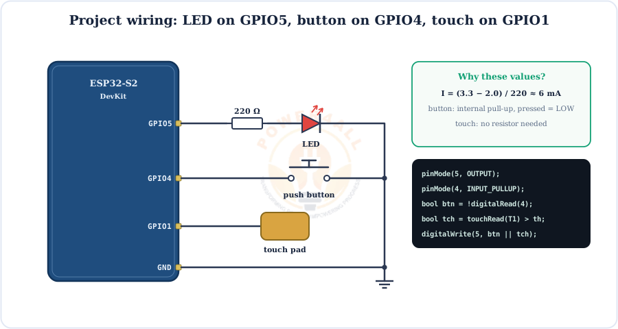
Project 1 — Touch lamp
uint32_t base;
bool lamp = false, wasTouched = false;

void setup() {
  pinMode(5, OUTPUT);
  delay(500);
  base = touchRead(T1);                // untouched baseline
}
void loop() {
  bool touched = touchRead(T1) > base * 1.2;   // 20% above baseline
  if (touched && !wasTouched) { lamp = !lamp; digitalWrite(5, lamp); }
  wasTouched = touched;
  delay(30);
}
Project 2 — Wi-Fi web-controlled LED
#include <WiFi.h>
#include <WebServer.h>
WebServer server(80);

void setup() {
  Serial.begin(115200);
  pinMode(5, OUTPUT);
  WiFi.begin("MySSID", "password");
  while (WiFi.status() != WL_CONNECTED) delay(500);
  server.on("/",    []() { server.send(200, "text/html", "<a href='/on'>ON</a> | <a href='/off'>OFF</a>"); });
  server.on("/on",  []() { digitalWrite(5, HIGH); server.send(200, "text/plain", "LED ON"); });
  server.on("/off", []() { digitalWrite(5, LOW);  server.send(200, "text/plain", "LED OFF"); });
  server.begin();
  Serial.println(WiFi.localIP());
}
void loop() { server.handleClient(); }
Project 3 — One-button USB keyboard
#include "USB.h"
#include "USBHIDKeyboard.h"
USBHIDKeyboard Keyboard;

void setup() {
  pinMode(4, INPUT_PULLUP);
  Keyboard.begin();
  USB.begin();
}
void loop() {
  if (digitalRead(4) == LOW) {        // pressed
    Keyboard.println("Hello from the ESP32-S2!");
    delay(500);                         // simple debounce / repeat delay
  }
}
Project 4 — Battery sensor that sleeps
RTC_DATA_ATTR int readings = 0;

void setup() {
  Serial.begin(115200);
  delay(1000);
  int mv = analogReadMilliVolts(2);    // GPIO2 = ADC1_CH1
  readings++;
  Serial.printf("Reading %d: %d mV\n", readings, mv);
  esp_sleep_enable_timer_wakeup(30ULL * 1000000);
  esp_deep_sleep_start();              // ~tens of µA until the next wake
}
void loop() {}
ESP32-S2 vs ESP32 vs ESP32-S3 vs ESP32-C3
All four chips do 2.4 GHz Wi-Fi at 3.3 V, but they differ in cores, Bluetooth and USB. Here is how to choose.
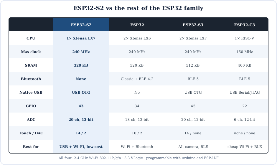
- Pick the ESP32-S2 for USB devices, Wi-Fi-only sensors, touch interfaces and the lowest cost per Wi-Fi node.
- Pick the original ESP32 when you need Bluetooth Classic (audio, serial SPP) or two cores.
- Pick the ESP32-S3 for camera, AI/vector maths, BLE 5 and native USB together.
- Pick the ESP32-C3 for the cheapest Wi-Fi + BLE with a RISC-V core.
Specifications
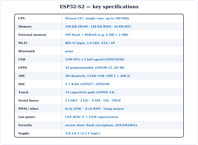
The ESP32-S2 at a glance.
| Parameter | Value |
|---|---|
| CPU | Xtensa LX7, single core, up to 240 MHz |
| On-chip memory | 320 KB SRAM, 128 KB ROM, 16 KB RTC SRAM |
| External memory | SPI flash + optional PSRAM (e.g. 4 MB + 2 MB on WROVER) |
| Wi-Fi | 802.11 b/g/n, 2.4 GHz, station / soft-AP |
| Bluetooth | None |
| USB | USB OTG 1.1 full-speed (GPIO19 D−, GPIO20 D+) |
| GPIO | 43 (GPIO0–21, GPIO26–46) |
| ADC | 20 channels, 13-bit SAR (ADC1 + ADC2) |
| DAC | 2 × 8-bit (GPIO17, GPIO18) |
| Touch | 14 capacitive pads (GPIO1–14) |
| Interfaces | 2 × UART, 2 × I2C, 4 × SPI, I2S, TWAI (CAN), LEDC (8 ch), RMT (4 ch), camera/LCD |
| Low power | ULP RISC-V + ULP FSM, deep-sleep and hibernation modes |
| Security | Secure boot, flash encryption, AES / SHA / RSA, HMAC, digital signature |
| Supply voltage | 3.0–3.6 V (3.3 V logic, not 5 V tolerant) |
Key Terms — Glossary
| Term | Meaning |
|---|---|
| SoC | System-on-chip: CPU, memory, radio and peripherals on one piece of silicon. |
| Xtensa LX7 | The 32-bit CPU core design (from Cadence) used in the ESP32-S2 and S3. |
| USB OTG | USB On-The-Go: a USB controller that can act as a device (and, with support, a host). |
| TinyUSB | Open-source USB stack used by the ESP32-S2 for CDC, HID, MSC and MIDI. |
| Strapping pin | A pin read once at reset to choose the boot mode or a hardware option. |
| GPIO matrix | Internal switchboard that connects peripheral signals to (almost) any pin. |
| PSRAM | Extra external RAM on the SPI bus (2 MB on the WROVER module). |
| ULP | Ultra-low-power coprocessor (RISC-V or FSM) that runs while the main CPU sleeps. |
| RTC GPIO | GPIO0–21 — pins in the always-on domain that can wake the chip. |
| LEDC | The LED-control PWM peripheral (8 channels). |
| TWAI | Two-Wire Automotive Interface — Espressif's CAN 2.0 controller. |
| Attenuation | ADC input scaling that sets the measurable voltage range. |
Frequently Asked Questions
Quick answers to the questions people ask most about the ESP32-S2.
What is the ESP32-S2?
A low-cost Wi-Fi system-on-chip from Espressif with a single-core 32-bit Xtensa LX7 at up to 240 MHz, 320 KB SRAM, 2.4 GHz Wi-Fi, native USB OTG, 43 GPIOs, a 13-bit ADC, two DACs and 14 touch pads. It is used in IoT devices, USB gadgets and battery-powered sensors.
Does the ESP32-S2 have Bluetooth?
No. It has 2.4 GHz Wi-Fi only — no Bluetooth or BLE radio. For Bluetooth choose the original ESP32 (Classic + BLE), the ESP32-S3 or the ESP32-C3 (BLE 5).
What is the difference between the ESP32 and the ESP32-S2?
The ESP32 has two Xtensa LX6 cores, 520 KB SRAM and Wi-Fi + Bluetooth, but no native USB. The ESP32-S2 has one Xtensa LX7 core, 320 KB SRAM and Wi-Fi without Bluetooth, and adds native USB OTG, 43 GPIOs, a 13-bit ADC, 14 touch pads and a RISC-V ULP coprocessor.
How many GPIO pins does the ESP32-S2 have?
43 programmable GPIOs: GPIO0–21 and GPIO26–46 (GPIO22–25 don't exist). GPIO26–32 normally connect to the module's flash and PSRAM, GPIO46 is input-only, and GPIO0, GPIO45 and GPIO46 are strapping pins.
What is special about the ESP32-S2 native USB?
It has a built-in full-speed USB OTG controller on GPIO19 (D−) and GPIO20 (D+). With TinyUSB it can appear to a computer as a serial port, keyboard, mouse, USB flash drive or MIDI device, and it can be programmed without a separate USB-to-UART chip.
Which pins are the ESP32-S2 strapping pins?
GPIO0, GPIO45 and GPIO46. GPIO0 HIGH at reset boots from flash; GPIO0 LOW (with GPIO46 LOW) enters download mode. GPIO45 selects the flash supply voltage (LOW = 3.3 V, the default). Avoid pulling these pins the wrong way during reset.
What is the ADC resolution of the ESP32-S2?
13 bits (0–8191), with 20 channels: ADC1 on GPIO1–10 and ADC2 on GPIO11–20. At the highest attenuation the useful range is about 0–2.5 V. ADC2 is shared with Wi-Fi, so use ADC1 pins when Wi-Fi is on.
How do I program the ESP32-S2 with the Arduino IDE?
Install the esp32 by Espressif Systems package in the Boards Manager, select ESP32S2 Dev Module or your board, choose the port and click Upload. If the board isn't detected, hold BOOT, tap RST, release BOOT and upload again.
Does the ESP32-S2 have a DAC?
Yes — two 8-bit DAC channels on GPIO17 (DAC1) and GPIO18 (DAC2). In Arduino, dacWrite(17, value) with 0–255 outputs a real voltage from about 0 to 3.3 V.
Is the ESP32-S2 5 V tolerant?
No. It runs on 3.0–3.6 V and its GPIOs are not 5 V tolerant. Use a resistor divider or level shifter for 5 V signals, and power dev boards from USB or the 5V pin, which feed the on-board 3.3 V regulator.
Conclusion & Key Takeaways
The ESP32-S2 trades Bluetooth and a second core for native USB, more GPIOs, better analog and lower power — making it the go-to chip for Wi-Fi USB gadgets and efficient IoT sensors.
LX7 @ 240 MHz
Single core, 320 KB SRAM.
Wi-Fi only
No Bluetooth.
Native USB
GPIO19/20, HID/CDC/MSC.
43 GPIOs
Avoid 26–32; straps 0/45/46.
Analog + touch
13-bit ADC, 2 DAC, 14 pads.
Low power
Deep sleep + ULP RISC-V.