STM32F103 Blue Pill
A tiny, dirt-cheap 32-bit ARM board that runs rings around an 8-bit Arduino. The Blue Pill is built on the STM32F103C8 — an ARM Cortex-M3 at 72 MHz with 64 KB flash, 20 KB SRAM, a real 12-bit ADC, USB and CAN. This guide covers the full board anatomy, a complete pinout with every port pin explained, 3.3 V logic & 5 V-tolerance, power, the buses, ST-Link SWD and serial programming, the BOOT jumpers, a Blue Pill vs Arduino Uno comparison, and code and mini-projects.
Complete Learning Path — STM32F103 Blue Pill
From board anatomy and the Cortex-M3 STM32F103C8, to a full port pinout with every pin detailed, 3.3 V logic, power, digital & analog I/O, PWM, the buses, ST-Link/SWD programming, the BOOT jumpers, Blue Pill vs Uno, code and mini-projects
What is the STM32F103 Blue Pill?
The STM32F103 Blue Pill is a tiny, very cheap development board built around the STM32F103C8T6 — a genuine 32-bit ARM Cortex-M3 microcontroller. For a couple of dollars you get far more speed, memory and peripherals than an 8-bit Arduino Uno.
It gets its nickname from the small blue PCB. It is the low-cost gateway into the STM32 world, and it works with the Arduino IDE (via the STM32duino core), STM32CubeIDE or PlatformIO.
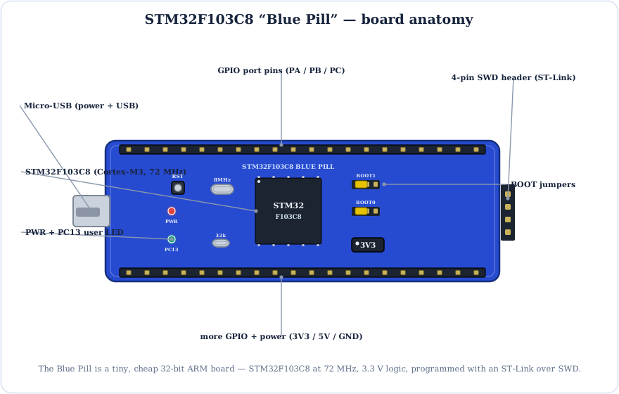
The Brain: STM32F103C8
At the centre sits the STM32F103C8T6 — a 32-bit ARM Cortex-M3 core clocked up to 72 MHz (multiplied by an internal PLL from the 8 MHz crystal), with hardware for USB, CAN and a rich set of timers and serial buses.
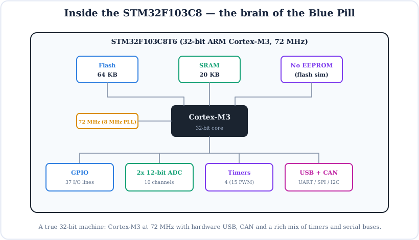
- Flash (64 KB) — stores your program. (The C8 is officially 64 KB; many boards actually have 128 KB of usable flash.)
- SRAM (20 KB) — working memory for variables — ten times the Uno's 2 KB.
- No EEPROM — there is no dedicated EEPROM; libraries emulate it in flash instead.
- 72 MHz Cortex-M3 — a 32-bit core, so maths and data handling are dramatically faster than an 8-bit AVR.
Full STM32F103 Blue Pill Pinout
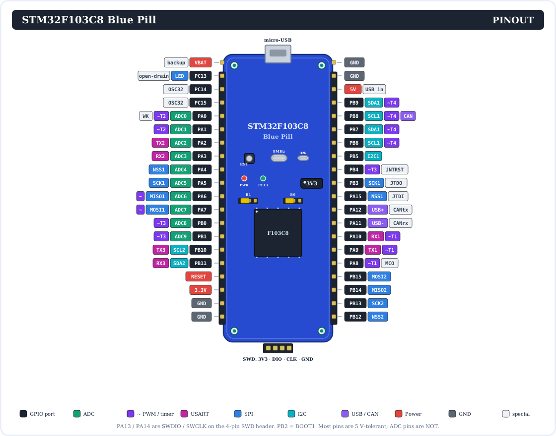
Here is the complete pinout. Unlike an Arduino, STM32 pins are named by port and number — PA0…PA15, PB0…PB15 and PC13…PC15 — and each has several alternate functions.
Prefer a simpler view? This colour-coded map groups the pins by function:
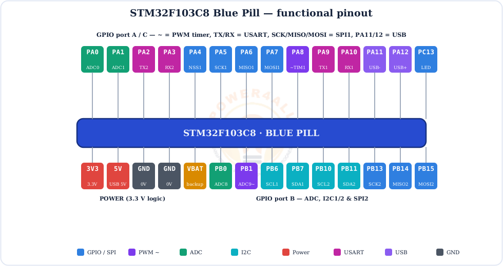
Every Pin Explained
Let's go through each group of pins. On the STM32 a single pin often has many roles — you pick one in software.
GPIO pins (PA / PB / PC)
37 general-purpose pins that read or write HIGH (3.3 V) or LOW (0 V) with pinMode(), digitalWrite() and digitalRead(). Each handles about 20 mA (25 mA max). They have configurable built-in pull-ups and pull-downs.
PC13
The on-board user LED — and it is active-low (LOW = on).
PB6 / PB7
I2C1 (SCL / SDA). Second bus I2C2 is on PB10/PB11.
PA9 / PA10
USART1 (TX / RX) — also the serial bootloader pins.
Timer pins (~)
Up to 15 PWM channels across TIM1–TIM4 on many PA/PB pins.
PA11 / PA12
Native USB D− / D+ (shared with the CAN controller).
Analog input pins (10 channels)
Two 12-bit ADCs share 10 external channels, each reading 0–3.3 V as 0–4095:
- PA0–PA7 (ADC channels 0–7) and PB0, PB1 (channels 8, 9).
- Read them with
analogRead(PA0); callanalogReadResolution(12)to get the full 12-bit range. - Warning: the ADC pins are not 5 V-tolerant — keep them at 3.3 V max.
The buses (and their pins)
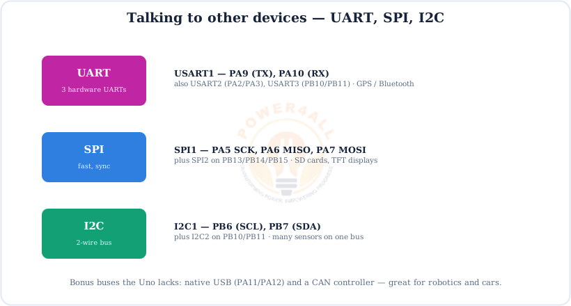
| Bus | Bus 1 pins | Bus 2 pins |
|---|---|---|
| UART | USART1: PA9 (TX) / PA10 (RX) | USART2 PA2/PA3, USART3 PB10/PB11 |
| SPI | SPI1: PA5 SCK, PA6 MISO, PA7 MOSI | SPI2: PB13 / PB14 / PB15 |
| I2C | I2C1: PB6 (SCL) / PB7 (SDA) | I2C2: PB10 / PB11 |
| USB / CAN | USB: PA11 (D−) / PA12 (D+) | CAN shares PA11 / PA12 |
Power & programming pins
5V (USB input / output), 3.3V (regulated out), GND, VBAT (backup domain), RESET, plus the 4-pin SWD header (3V3, SWDIO = PA13, SWCLK = PA14, GND) for the ST-Link. There is no barrel jack.
STM32 vs Arduino wiring
STM32 pins are referred to by port name, not a single number — use PA5, PB7, PC13 in your code, not D5. A pin can only do one alternate function at a time, so plan which peripheral uses which pin.
3.3 V Logic — and the 5 V Trap
The single biggest difference from an Uno: the Blue Pill runs at 3.3 V. Most digital pins are 5 V-tolerant as inputs, but the analog pins are not — getting this wrong can damage the chip.
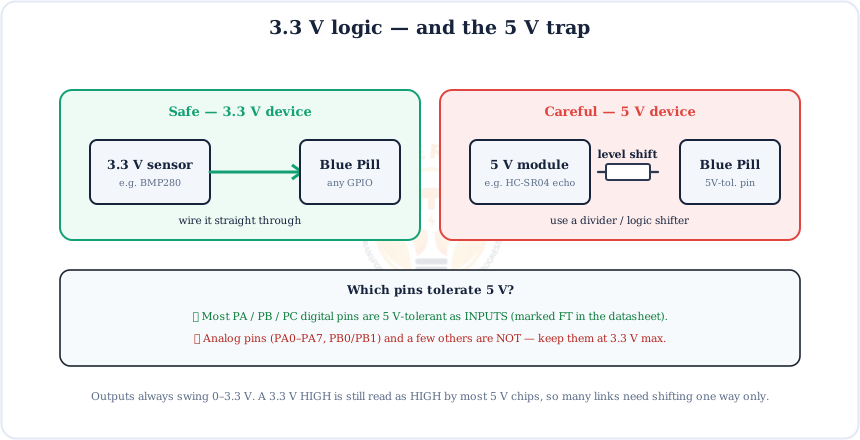
- 5 V-tolerant (FT) pins — most PA/PB/PC digital pins can safely read a 5 V input.
- NOT 5 V-tolerant — the analog pins PA0–PA7, PB0 and PB1, plus a few others.
- Outputs always swing 0–3.3 V. A 3.3 V HIGH is still read as HIGH by most 5 V chips, so many links only need shifting in one direction.
Powering the Blue Pill
Power it from micro-USB (5 V) or feed 5 V into the 5V pin. An on-board AMS1117 regulator makes the 3.3 V the chip and every GPIO run on.
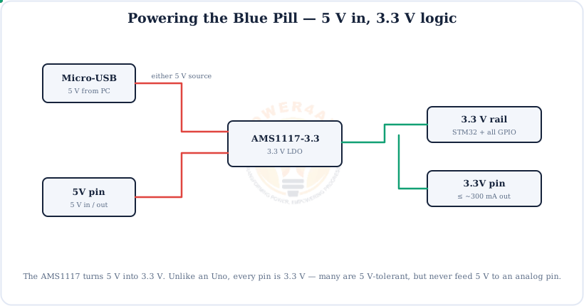
Feeding 3.3 V directly
If you already have a clean 3.3 V supply (e.g. from an ST-Link), you can power the board through the 3.3V pin and skip the on-board regulator. Don't power both USB and an external 3.3 V at the same time.
Digital I/O
Output a HIGH/LOW to drive an LED or relay, or read a HIGH/LOW input from a button or sensor — all at 3.3 V.
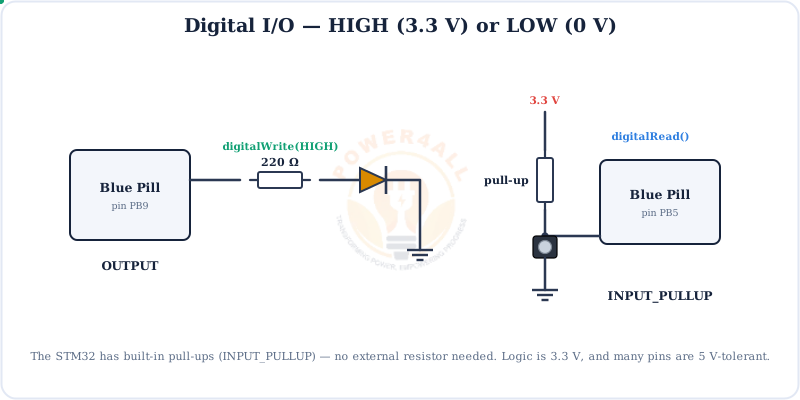
INPUT_PULLUP — no external resistor needed.// digital output + input (STM32, 3.3 V) void setup() { pinMode(PB9, OUTPUT); // LED pin pinMode(PB5, INPUT_PULLUP); // button to GND } void loop() { digitalWrite(PB9, !digitalRead(PB5)); // LED follows the button }
PWM Output (~)
PWM fakes an analog voltage by switching a pin on and off fast. The STM32F103 has powerful timers giving up to 15 PWM channels across many PA/PB pins.
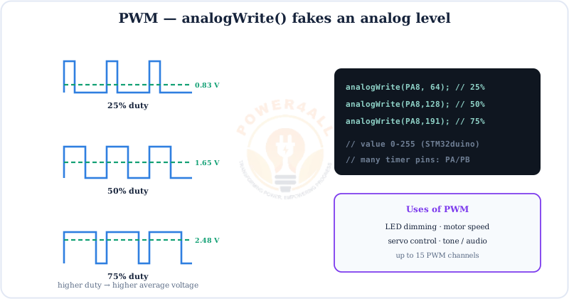
analogWrite(pin, 0–255) on any timer pin such as PA8.// fade an LED on a PWM/timer pin (PA8) void setup() { pinMode(PA8, OUTPUT); } void loop() { for (int v = 0; v <= 255; v++) { analogWrite(PA8, v); delay(5); } for (int v = 255; v >= 0; v--) { analogWrite(PA8, v); delay(5); } }
Analog Input (ADC)
The Blue Pill's 12-bit ADC is far finer than the Uno's 10-bit one. Each reading turns 0–3.3 V into 0–4095 — about 0.8 mV per step.
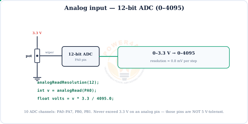
v * 3.3 / 4095.0. Keep analog pins at 3.3 V max.// read a 12-bit analog input on PA0 void setup() { Serial.begin(9600); analogReadResolution(12); // full 0..4095 range } void loop() { int raw = analogRead(PA0); // 0..4095 float volts = raw * 3.3 / 4095.0; Serial.println(volts); delay(200); }
UART, SPI & I2C
The STM32F103 is generous with buses: three UARTs, two SPI and two I2C — plus native USB and CAN that an Uno simply doesn't have.
How Code Gets onto the Blue Pill
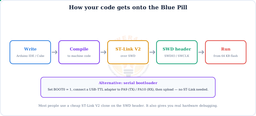
Unlike an Arduino, the Blue Pill usually needs a small ST-Link V2 programmer on its 4-pin SWD header. You can also upload over serial using the BOOT jumper.
The ST-Link connection
Wire the ST-Link to the SWD header: 3V3→3V3, SWDIO→DIO, SWCLK→CLK, GND→GND. In the Arduino IDE, install the “STM32 MCU based boards” core, pick Generic STM32F1 → Blue Pill, and set the upload method to STLink.
The BOOT0 / BOOT1 Jumpers
The two little yellow jumpers decide where the chip starts running when it powers up or resets.
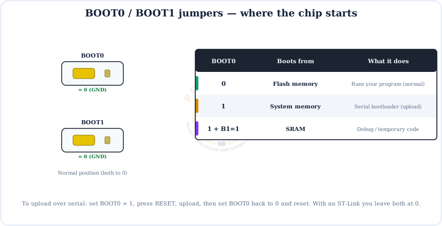
For everyday work with an ST-Link, leave both jumpers at 0. Only move BOOT0 to 1 when you want to upload over serial without a programmer — then set it back and reset.
Blue Pill vs Arduino Uno vs Nano
Why choose a Blue Pill over an Arduino Uno? Speed, memory and peripherals — for a similar price. The trade-off is 3.3 V wiring and needing an ST-Link.
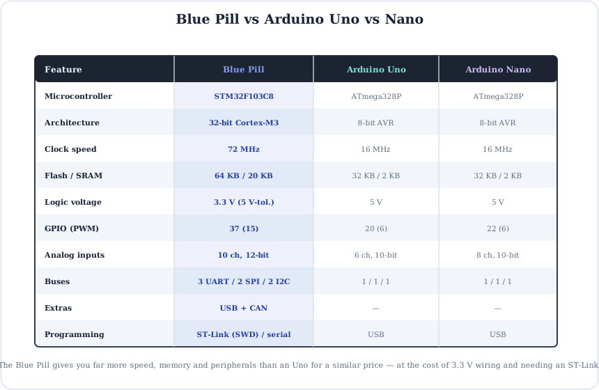
Choose the Blue Pill when you need real 32-bit speed, more memory, a fine ADC or USB/CAN; choose the Uno/Nano for 5 V shields, simple USB uploading and the biggest beginner ecosystem. For a 32-bit ARM board that still uploads over USB like an Arduino, see the Arduino Due.
Code Examples
The everyday building blocks, written for the STM32duino core.
1. Blink the on-board PC13 LED (active-low)
void setup() { pinMode(PC13, OUTPUT); }
void loop() {
  digitalWrite(PC13, LOW);  delay(1000);   // LED on
  digitalWrite(PC13, HIGH); delay(1000);   // LED off
}
2. Print to the Serial Monitor over USB
void setup() {
  Serial.begin(115200);           // USB CDC serial
}
void loop() { Serial.println(millis()); delay(1000); }
3. Talk to a module on USART1 (PA9 / PA10)
// Serial1 is USART1 on PA9 (TX) / PA10 (RX)
void setup() {
  Serial.begin(115200);      // USB to PC
  Serial1.begin(9600);       // module on PA9/PA10
}
void loop() {
  if (Serial1.available()) Serial.write(Serial1.read());
}
Beginner Mini-Projects
Four small builds that show off the Blue Pill's strengths.
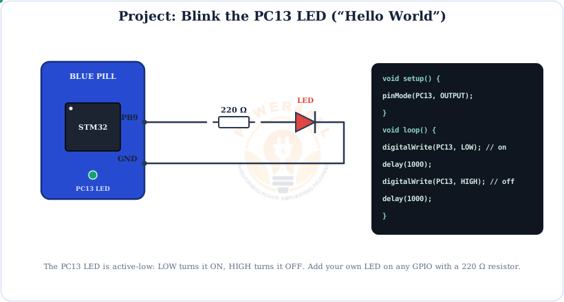
Project 1 — Blink the PC13 LED
void setup() { pinMode(PC13, OUTPUT); }
void loop() {
  digitalWrite(PC13, LOW);  delay(500);
  digitalWrite(PC13, HIGH); delay(500);
}
Project 2 — Button with a built-in pull-up
void setup() {
  pinMode(PC13, OUTPUT);
  pinMode(PB5, INPUT_PULLUP);
}
void loop() {
  if (digitalRead(PB5) == LOW) digitalWrite(PC13, LOW);   // pressed = LED on
  else                          digitalWrite(PC13, HIGH);
}
Project 3 — 12-bit potentiometer meter
void setup() {
  Serial.begin(115200);
  analogReadResolution(12);
}
void loop() {
  int raw = analogRead(PA0);
  Serial.println(raw * 3.3 / 4095.0, 3);   // volts
  delay(100);
}
Project 4 — I2C scanner on PB6/PB7
Wire library.#include <Wire.h> void setup() { Serial.begin(115200); Wire.begin(); // I2C1: SCL=PB6, SDA=PB7 } void loop() { for (byte a = 1; a < 127; a++) { Wire.beginTransmission(a); if (Wire.endTransmission() == 0) { Serial.print("found 0x"); Serial.println(a, HEX); } } delay(2000); }
Specifications
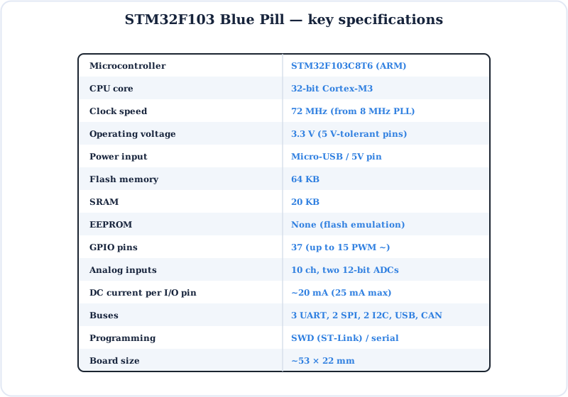
The STM32F103 Blue Pill at a glance.
Key Terms — Glossary
| Term | Meaning |
|---|---|
| STM32F103C8 | The Blue Pill's 32-bit ARM Cortex-M3 microcontroller. |
| Cortex-M3 | ARM's 32-bit core used in the STM32F103, running at 72 MHz. |
| Port pin (PAx) | STM32 naming: port letter + number, e.g. PA5, PB7, PC13. |
| SWD | Serial Wire Debug — the 2-wire programming/debug interface (SWDIO, SWCLK). |
| ST-Link | The small USB programmer/debugger that talks SWD to the chip. |
| BOOT0 / BOOT1 | Jumpers that pick boot from flash, system memory or SRAM. |
| 5 V-tolerant (FT) | A pin that can safely accept a 5 V input despite 3.3 V logic. |
| PC13 LED | The on-board user LED — active-low (LOW = on). |
| AMS1117 | The on-board LDO that makes 3.3 V from the 5 V supply. |
| STM32duino | The Arduino core that lets you program STM32 boards with Arduino code. |
Frequently Asked Questions
Quick answers to the questions people ask most about the STM32F103 Blue Pill.
What is the STM32F103 Blue Pill?
A tiny, very cheap board built on the STM32F103C8T6, a 32-bit ARM Cortex-M3 at 72 MHz with 64 KB flash and 20 KB SRAM. It has 37 GPIO, a 12-bit ADC, many PWM timers, three UARTs, two SPI, two I2C, USB and CAN — far more capable than an 8-bit Arduino Uno, but it runs at 3.3 V.
Blue Pill vs Arduino Uno — what's different?
The Blue Pill is 32-bit at 72 MHz with 64 KB flash and 20 KB SRAM; the Uno is 8-bit at 16 MHz with 32 KB flash and 2 KB SRAM. The Blue Pill adds a 12-bit ADC, more buses, USB and CAN, but runs at 3.3 V and usually needs an ST-Link to program.
How do I program it?
Most people use a cheap ST-Link V2 on the 4-pin SWD header (3V3, SWDIO, SWCLK, GND), which also enables hardware debugging. You can also upload over serial by setting BOOT0 = 1 and connecting a USB-to-TTL adapter to PA9 (TX) / PA10 (RX). Write ordinary Arduino sketches with the STM32duino core.
Is it 5 V-tolerant?
It runs at 3.3 V. Most digital PA/PB/PC pins are 5 V-tolerant as inputs (marked FT), so they can read 5 V signals. But the analog pins (PA0–PA7, PB0, PB1) are NOT 5 V-tolerant, and outputs only swing 0–3.3 V. Never put 5 V on an analog pin.
What do the BOOT0 / BOOT1 jumpers do?
They pick where the chip starts. BOOT0 = 0 boots from flash and runs your program (normal). BOOT0 = 1 boots system memory and runs the serial bootloader for uploading. BOOT0 = 1 with BOOT1 = 1 boots from SRAM (rare). With an ST-Link, leave both at 0.
Which pin is the on-board LED?
The user LED is on PC13 and is active-low: digitalWrite(PC13, LOW) turns it on and HIGH turns it off. A separate red PWR LED lights whenever the board is powered.
How many analog inputs and how fine are they?
Two 12-bit ADCs share 10 external channels on PA0–PA7, PB0 and PB1. Readings run 0–4095 over 0–3.3 V (~0.8 mV per step). Call analogReadResolution(12) to use the full range.
Where are UART, SPI and I2C?
USART1 on PA9/PA10 (plus USART2 PA2/PA3, USART3 PB10/PB11); SPI1 on PA5/PA6/PA7 (plus SPI2 PB13/PB14/PB15); I2C1 on PB6/PB7 (plus I2C2 PB10/PB11). Native USB is on PA11/PA12, shared with the CAN controller.
Conclusion & Key Takeaways
The STM32F103 Blue Pill is the cheapest way into 32-bit ARM — huge power for the price, as long as you respect its 3.3 V world.
Cortex-M3
32-bit, 72 MHz.
64 / 20 KB
Flash / SRAM.
3.3 V logic
Many 5 V-tolerant pins.
12-bit ADC
USB & CAN too.
ST-Link / SWD
Or serial bootloader.
PC13 LED
Active-low.