Arduino Nano 33 IoT
A Nano-sized board with Wi-Fi and Bluetooth built in. The Arduino Nano 33 IoT pairs a 32-bit SAMD21 Cortex-M0+ with a u-blox NINA-W102 radio, an LSM6DS3 motion sensor and an ATECC608A crypto chip. This guide covers the full board anatomy, a complete pinout with every pin explained, 3.3 V logic and power, Wi-Fi and BLE, and ends with code examples and IoT mini-projects.
Complete Learning Path — Arduino Nano 33 IoT
From board anatomy and the SAMD21, to a full pinout with every pin detailed, 3.3 V logic, power, analog, buses, Wi-Fi, BLE, the IMU, uploading, code examples and mini-projects
What is the Arduino Nano 33 IoT?
The Arduino Nano 33 IoT is a tiny Wi-Fi and Bluetooth microcontroller board in the classic 45 × 18 mm Nano footprint. A 32-bit SAMD21G18A runs your sketch, while a u-blox NINA-W102 module handles the radio — so you can put sensors on the internet, talk to a phone over BLE or send data to the cloud from a board smaller than a stick of gum.
The “33” in the name means 3.3 V: unlike the original Arduino Nano, every pin works at 3.3 V logic. The “IoT” part comes from three extras packed onto the board: the Wi-Fi/BLE module, a 6-axis LSM6DS3 IMU (accelerometer + gyroscope) and an ATECC608A secure element for encrypted cloud connections.
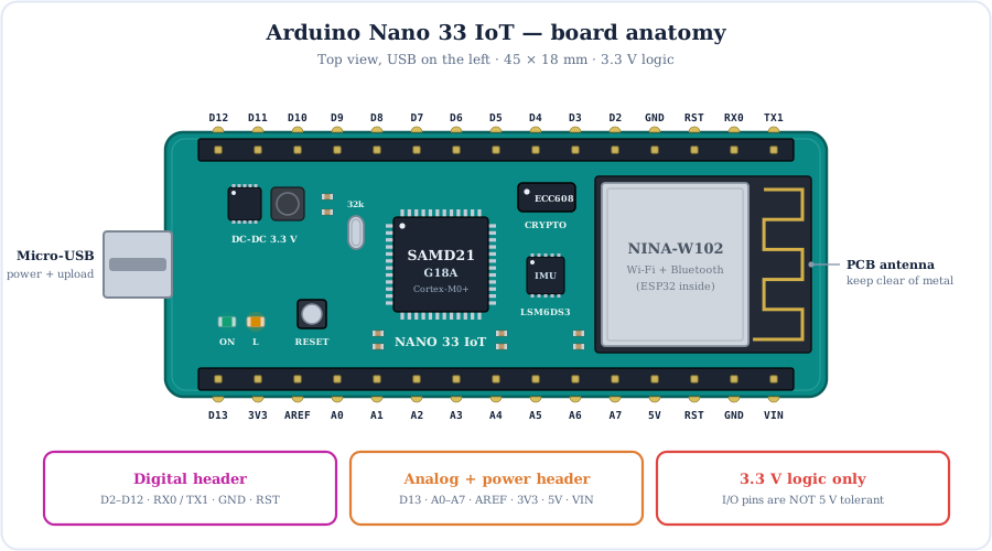
Micro-USB
Power, sketch upload and the Serial Monitor. The SAMD21 has native USB, so there is no separate USB-serial chip.
DC-DC buck
A switching step-down regulator turns USB 5 V or VIN (up to 21 V) into the 3.3 V rail — efficient and cool.
NINA-W102
u-blox module with its own ESP32 chip, flash and PCB antenna. It runs the Wi-Fi/BLE firmware only.
LSM6DS3
6-axis IMU — measures acceleration and rotation for tilt, steps and gestures.
ATECC608A
Crypto chip that keeps private keys in hardware for secure TLS/cloud logins.
Castellated headers
2 × 15 pins, 0.1″ pitch. Solder pin headers for a breadboard or solder the edge pads straight onto your own PCB.
How the Nano 33 IoT Is Wired Inside
The Nano 33 IoT is really a small network of chips. The SAMD21 sits in the middle and talks to every other part over a different link.
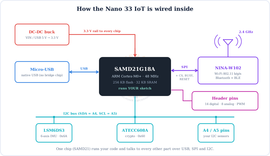
| Link | Between | What it carries |
|---|---|---|
| Native USB | SAMD21 ↔ PC | Uploads and the Serial monitor (USB CDC). No CH340 or 16U2 bridge. |
| SPI + control lines | SAMD21 ↔ NINA-W102 | Wi-Fi and BLE commands and data, used by WiFiNINA and ArduinoBLE. These lines are internal and do not use your header pins. |
| I2C (A4 / A5) | SAMD21 ↔ LSM6DS3, ATECC608A | IMU readings (address 0x6A) and crypto operations (0x60). The same bus is on the header for your sensors. |
| 3.3 V rail | Buck regulator → all chips | One supply for the MCU, radio, sensors and the 3V3 pin. |
The Brain: SAMD21G18A (ARM Cortex-M0+)
The Microchip SAMD21G18A is a 32-bit ARM chip. It is a big step up from the 8-bit ATmega328P on the Uno: 3× the clock, 8× the flash and 16× the RAM.
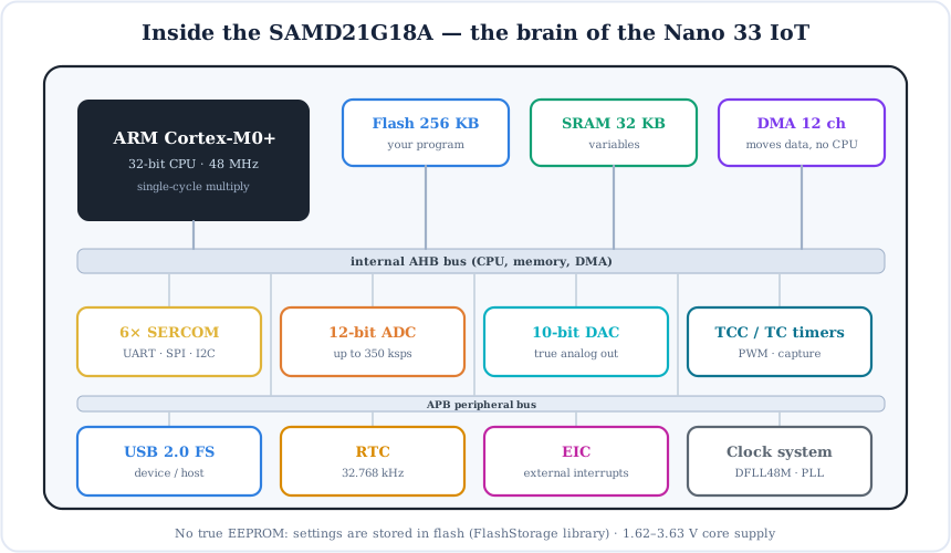
- Flash (256 KB) — holds your program. About 8 KB is taken by the USB bootloader.
- SRAM (32 KB) — room for Wi-Fi buffers, JSON strings and sensor arrays that would never fit on an Uno.
- No EEPROM — to keep settings across power cycles, save them to flash with the
FlashStoragelibrary. - 6 SERCOMs — flexible serial blocks. Each can become a UART, SPI or I2C port, so you can add extra buses on other pins.
- 12-bit ADC and 10-bit DAC — finer analog readings and a real analog output on A0.
- DMA, RTC and 32.768 kHz crystal — move data without the CPU and keep accurate time for low-power logging.
Full Arduino Nano 33 IoT Pinout
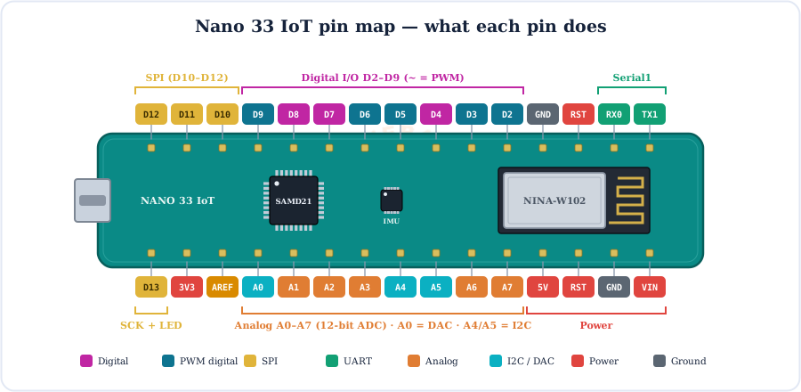
Here is the complete pinout. Every pin shows its Arduino number, the SAMD21 port pin (PAxx / PBxx) and its alternate functions: PWM, analog, DAC, SPI, I2C, UART or power.
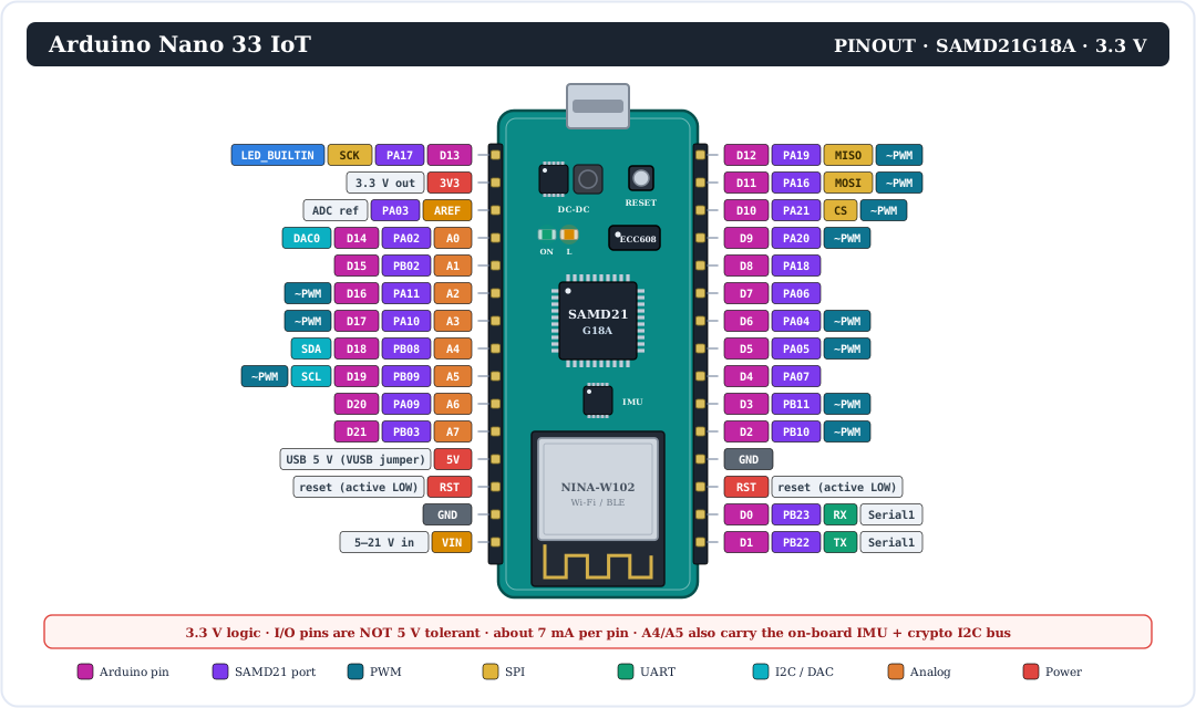
Want a quicker view? This map groups the pins by what they do:
Every Pin Explained
Now let's go through each group of pins and what it does. Remember: every signal pin is 3.3 V and can supply only about 7 mA.
Digital pins (D0–D13)
14 general-purpose pins that read or write HIGH (3.3 V) or LOW (0 V) with pinMode(), digitalWrite() and digitalRead(). Internal pull-up and pull-down resistors are available (INPUT_PULLUP, INPUT_PULLDOWN). Some pins have special jobs:
D0 (RX) & D1 (TX)
Hardware UART Serial1. Unlike the Uno, these pins are not shared with USB, so they are free for GPS or another MCU.
PWM pins (~)
D2, D3, D5, D6, D9, D10, D11, D12 plus A2, A3, A5 — 11 in total. Use analogWrite(pin, 0–255).
D10–D13
SPI bus: D11 = MOSI, D12 = MISO, D13 = SCK, D10 is the usual chip-select.
D13
Drives the on-board orange “L” LED (LED_BUILTIN). It is also SPI SCK, so the LED flickers during SPI traffic.
Interrupts
The SAMD21's EIC lets most pins trigger attachInterrupt(). Check the Arduino reference for the exact pins before you design around one.
Analog pins (A0–A7)
8 inputs connected to a 12-bit ADC. By default analogRead() returns 0–1023 (10-bit, Uno-compatible). Call analogReadResolution(12) to get the full 0–4095 over 0–3.3 V. All of them can also be used as digital pins D14–D21.
- A0 = DAC0 — a real 10-bit digital-to-analog converter (true analog voltage, not PWM).
- A4 = SDA and A5 = SCL — the I2C bus, already shared with the on-board IMU and crypto chip and fitted with pull-up resistors. Avoid using A4/A5 as plain analog inputs.
- A6 and A7 — unlike the classic Nano, these also work as digital pins.
- AREF — optional external reference voltage for the ADC (never above 3.3 V).
Power & control pins
| Pin | What it does |
|---|---|
| VIN | Power input, 5–21 V, into the on-board DC-DC buck (for example a 2S Li-ion pack or a 9–12 V adapter). |
| 5V | Not connected by default. Bridge the VUSB jumper on the back and it carries USB 5 V (only when powered from USB). |
| 3V3 | Regulated 3.3 V output from the buck — powers 3.3 V sensors and modules. |
| GND | Ground (0 V). There are two GND pins, one on each header. |
| RST | Reset, active LOW. Pull to GND to restart; two quick pulses enter the bootloader. |
| AREF | ADC reference input (PA03). |
3.3 V Logic — the #1 Rule
The Nano 33 IoT is not 5 V tolerant. Connecting a 5 V signal straight to a pin can permanently damage the SAMD21. Here are two safe ways to mix 3.3 V and 5 V parts.
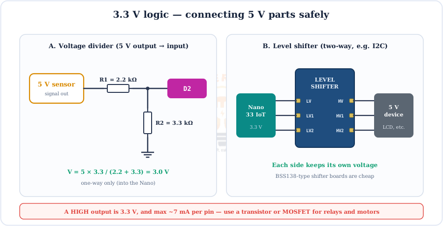
Voltage divider: Vout = Vin × R2 / (R1 + R2) = 5 V × 3.3 kΩ / (2.2 kΩ + 3.3 kΩ) = 3.0 V
Driving loads: a pin gives only ~7 mA at 3.3 V. That is enough for an LED with a 220–330 Ω resistor, but relays, motors and LED strips need a transistor or logic-level MOSFET — see our transistor-as-switch calculator and MOSFET guide.
Powering the Nano 33 IoT
There are two ways to power the board: micro-USB (5 V) or the VIN pin (5–21 V). Both feed a switching buck converter that makes a clean 3.3 V rail for every chip.
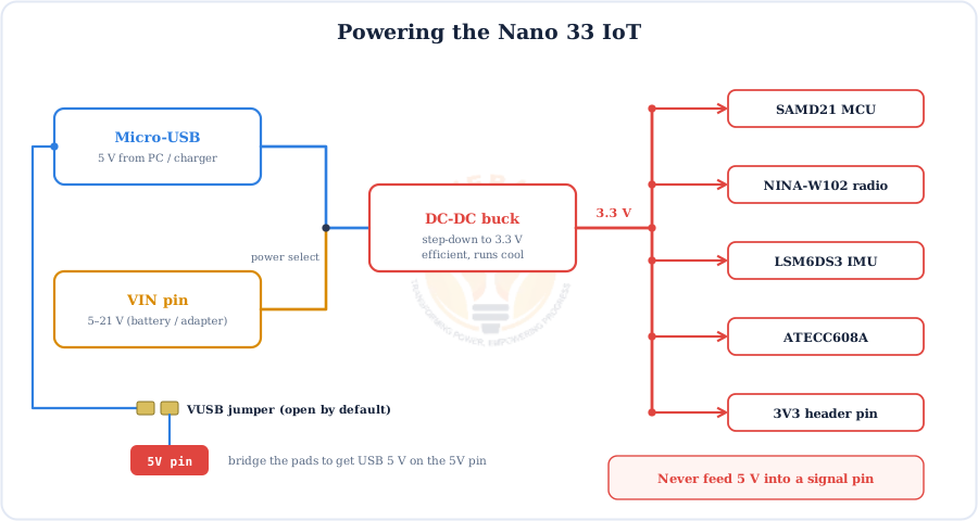
- Why a buck converter? A linear regulator would turn most of 12 V into heat. The switching buck is far more efficient, which matters for battery projects and Wi-Fi current peaks.
- Wi-Fi current — the radio draws short bursts of current when transmitting. Use a good USB cable and a supply with some headroom.
- 5 V modules — if a sensor needs 5 V power, bridge VUSB and power from USB, or use an external 5 V supply with a shared GND and level-shift its signals.
PWM, ADC and the True DAC
The SAMD21 gives the Nano 33 IoT better analog features than an AVR board: 11 PWM pins, a 12-bit ADC and a real DAC on A0.
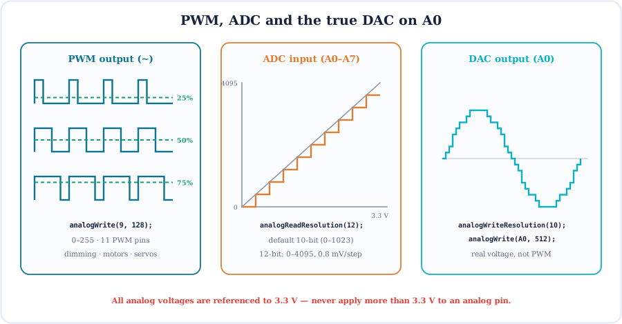
| Feature | Pins | Function | Range |
|---|---|---|---|
| PWM | D2, D3, D5, D6, D9–D12, A2, A3, A5 | analogWrite(pin, v) | 0–255 (default 8-bit) |
| ADC | A0–A7 | analogRead(pin) | 0–1023, or 0–4095 after analogReadResolution(12) |
| DAC | A0 only | analogWrite(A0, v) | 0–1023 after analogWriteResolution(10) → 0–3.3 V |
At 12 bits each ADC step is 3.3 V / 4096 ≈ 0.8 mV. For a potentiometer, connect its ends to 3V3 and GND (not 5 V), with the wiper on an analog pin.
Communication: USB Serial, UART, SPI & I2C
Four ways to talk to the world — and thanks to native USB, the hardware UART stays free for your own devices.
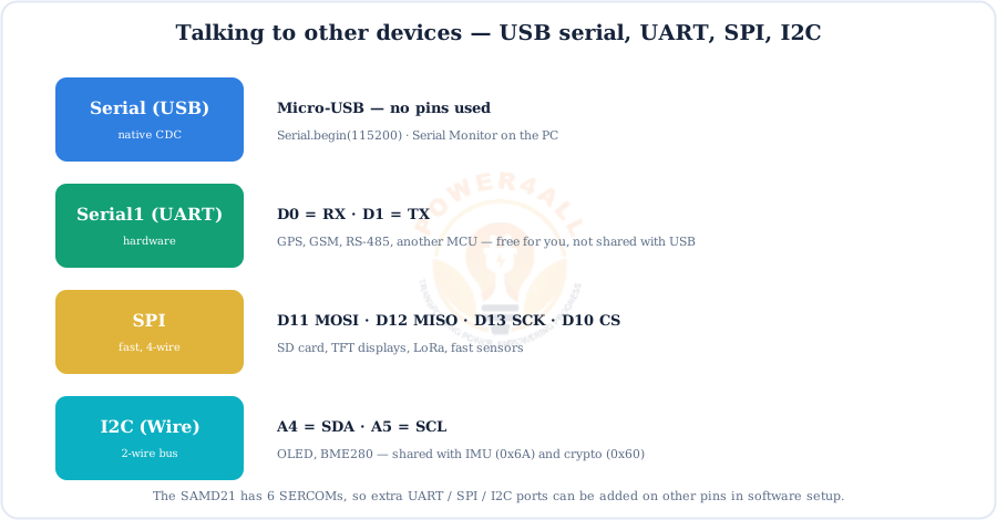
Serial = USB, Serial1 = D0/D1, SPI on D10–D13, I2C (Wire) on A4/A5.Tip: when you add an I2C sensor, make sure its address doesn't clash with the IMU (0x6A) or the crypto chip (0x60). Our pull-up resistor calculator helps when you add long I2C wires.
Wi-Fi with the NINA-W102 and WiFiNINA
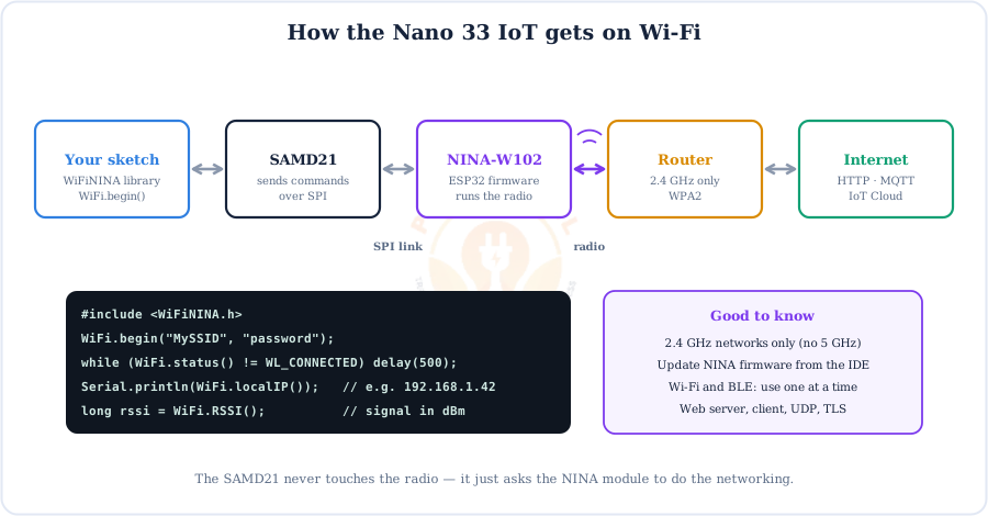
The SAMD21 never touches the radio itself. It sends commands over SPI to the NINA-W102, which runs Wi-Fi firmware on its own ESP32 and joins your 2.4 GHz network.
- Library: install
WiFiNINA. It providesWiFiClient,WiFiServer,WiFiUDPandWiFiSSLClientfor HTTPS/TLS. - Networks: 802.11 b/g/n on 2.4 GHz only — a 5 GHz-only router won't be found.
- Firmware: keep the NINA firmware up to date with the IDE's firmware updater tool so new TLS certificates and fixes are included.
- Cloud: the board works with Arduino IoT Cloud, MQTT brokers (e.g. with
ArduinoMqttClient) and plain HTTP APIs.
Bluetooth Low Energy (BLE)
The same NINA module also speaks Bluetooth. With the ArduinoBLE library the board becomes a BLE peripheral that a phone app (the central) can read, write and subscribe to.
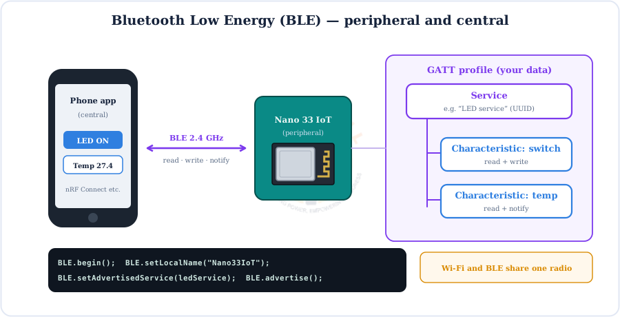
One radio, one job: Wi-Fi and BLE share the NINA-W102, so a sketch uses one at a time. Call BLE.end() before WiFi.begin() (or WiFi.end() before BLE.begin()) if you need to switch.
The Built-in IMU and Crypto Chip
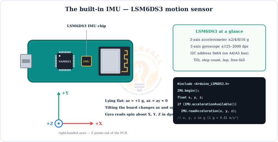
Two extra chips make the Nano 33 IoT useful straight out of the box: an LSM6DS3 motion sensor and an ATECC608A secure element.
Accelerometer
±2/4/8/16 g. At rest it reads gravity, so it tells you tilt, and it spots taps, shakes and free-fall.
Gyroscope
±125 to ±2000 dps. Measures how fast the board rotates — great for gestures and balancing robots.
ATECC608A
Stores private keys in hardware at I2C address 0x60. Used by ArduinoECCX08 and IoT Cloud for secure certificate-based logins.
How Code Gets onto the Nano 33 IoT
Install the right board package once, and uploading works just like any Arduino — but over the SAMD21's native USB.
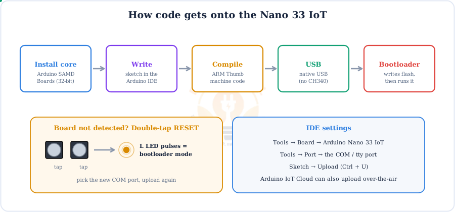
- Arduino IDE → Tools → Board → Boards Manager → install Arduino SAMD Boards (32-bits ARM Cortex-M0+).
- Select Arduino Nano 33 IoT and its port (COM on Windows,
/dev/ttyACM*on Linux). - Click Upload. The port may briefly change as the board resets into the bootloader — that's normal.
- If a crashed sketch hides the port, double-tap RESET, pick the new port and upload again.
Code Examples
Short, copy-paste sketches for each feature of the board.
1. Blink the on-board LED
void setup() {
  pinMode(LED_BUILTIN, OUTPUT);       // D13, orange "L" LED
}
void loop() {
  digitalWrite(LED_BUILTIN, HIGH);
  delay(500);
  digitalWrite(LED_BUILTIN, LOW);
  delay(500);
}
2. Connect to Wi-Fi and print the IP address
#include <WiFiNINA.h>
char ssid[] = "MySSID";
char pass[] = "password";

void setup() {
  Serial.begin(115200);
  while (!Serial);                    // wait for the Serial Monitor (remove on battery)
  while (WiFi.begin(ssid, pass) != WL_CONNECTED) {
    Serial.println("Connecting...");
    delay(2000);
  }
  Serial.print("IP: ");   Serial.println(WiFi.localIP());
  Serial.print("RSSI: "); Serial.println(WiFi.RSSI());  // signal in dBm
}
void loop() {}
3. Read the IMU (accelerometer)
#include <Arduino_LSM6DS3.h>

void setup() {
  Serial.begin(115200);
  if (!IMU.begin()) { Serial.println("IMU not found"); while (1); }
}
void loop() {
  float x, y, z;
  if (IMU.accelerationAvailable()) {
    IMU.readAcceleration(x, y, z);     // values in g
    Serial.print(x); Serial.print('\t');
    Serial.print(y); Serial.print('\t');
    Serial.println(z);
  }
  delay(100);
}
4. 12-bit ADC in, true DAC out
void setup() {
  Serial.begin(115200);
  analogReadResolution(12);          // 0..4095
  analogWriteResolution(10);         // DAC 0..1023
}
void loop() {
  int raw = analogRead(A1);            // pot wiper on A1 (ends on 3V3 and GND)
  float volts = raw * 3.3 / 4095.0;
  Serial.println(volts, 3);
  analogWrite(A0, raw >> 2);           // same level out of the DAC on A0
  delay(200);
}
Beginner IoT Mini-Projects
Put it all together. Each project needs only a few cheap parts, and the code is complete — upload and go.
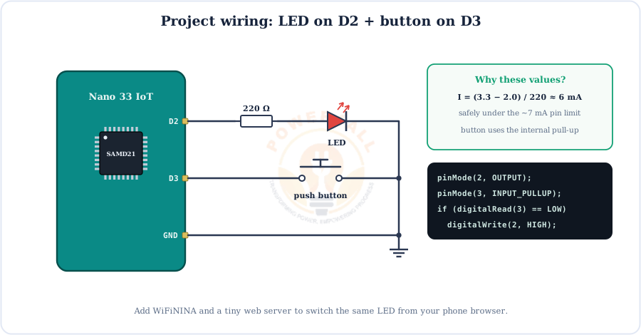
Project 1 — Wi-Fi web-controlled LED
#include <WiFiNINA.h>
char ssid[] = "MySSID", pass[] = "password";
WiFiServer server(80);

void setup() {
  pinMode(2, OUTPUT);
  Serial.begin(115200);
  while (WiFi.begin(ssid, pass) != WL_CONNECTED) delay(2000);
  server.begin();
  Serial.println(WiFi.localIP());      // open this address in a browser
}
void loop() {
  WiFiClient client = server.available();
  if (!client) return;
  String req = client.readStringUntil('\r');   // e.g. "GET /on HTTP/1.1"
  if (req.indexOf("GET /on")  >= 0) digitalWrite(2, HIGH);
  if (req.indexOf("GET /off") >= 0) digitalWrite(2, LOW);
  client.println("HTTP/1.1 200 OK");
  client.println("Content-Type: text/html");
  client.println();
  client.println("<h1>Nano 33 IoT</h1><a href='/on'>ON</a> | <a href='/off'>OFF</a>");
  delay(1);
  client.stop();
}
Project 2 — Tilt alarm with the IMU
#include <Arduino_LSM6DS3.h>

void setup() {
  pinMode(2, OUTPUT);
  if (!IMU.begin()) while (1);
}
void loop() {
  float x, y, z;
  if (IMU.accelerationAvailable()) {
    IMU.readAcceleration(x, y, z);
    bool tilted = (z < 0.7);        // cos(45°) ≈ 0.707 g
    digitalWrite(2, tilted ? HIGH : LOW);
  }
}
Project 3 — Phone-controlled LED over BLE
#include <ArduinoBLE.h>
BLEService ledService("19B10000-E8F2-537E-4F6C-D104768A1214");
BLEByteCharacteristic switchChar("19B10001-E8F2-537E-4F6C-D104768A1214", BLERead | BLEWrite);

void setup() {
  pinMode(LED_BUILTIN, OUTPUT);
  if (!BLE.begin()) while (1);
  BLE.setLocalName("Nano33IoT");
  BLE.setAdvertisedService(ledService);
  ledService.addCharacteristic(switchChar);
  BLE.addService(ledService);
  switchChar.writeValue(0);
  BLE.advertise();
}
void loop() {
  BLEDevice central = BLE.central();
  while (central && central.connected()) {
    if (switchChar.written())
      digitalWrite(LED_BUILTIN, switchChar.value() ? HIGH : LOW);
  }
}
Project 4 — Button counter on the Serial Monitor
int count = 0;
bool last = HIGH;

void setup() {
  pinMode(3, INPUT_PULLUP);
  Serial.begin(115200);
}
void loop() {
  bool now = digitalRead(3);
  if (last == HIGH && now == LOW) {   // falling edge = press
    count++;
    Serial.print("Presses: "); Serial.println(count);
    delay(30);                          // crude debounce
  }
  last = now;
}
Nano 33 IoT vs Other Nano Boards
All of these boards share the same 45 × 18 mm footprint, so choosing between them is about wireless, speed and logic voltage.
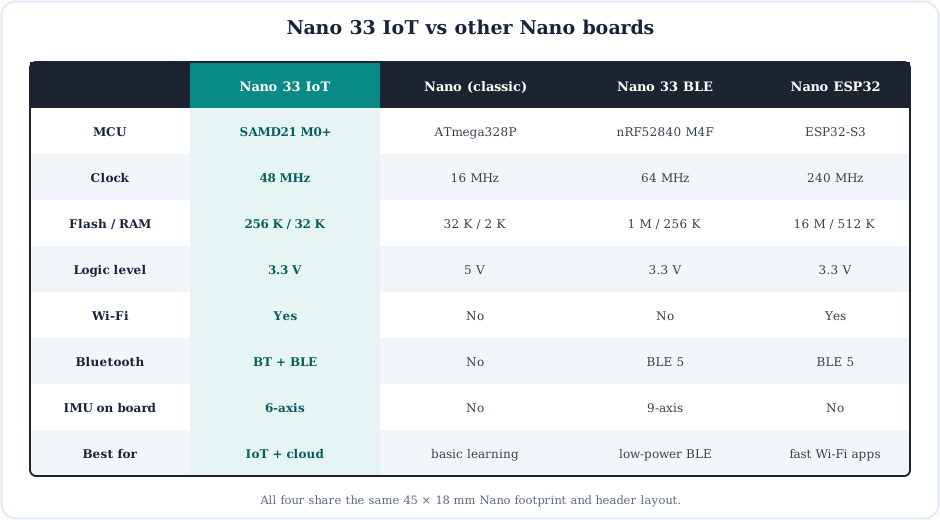
- Pick the Nano 33 IoT for Wi-Fi + BLE with the simple Arduino API, a built-in IMU and secure cloud connections.
- Pick the classic Nano when you need 5 V logic for older shields and modules.
- Pick the Nano 33 BLE for low-power Bluetooth projects and TinyML (more RAM, 9-axis IMU, no Wi-Fi).
- Pick an ESP32 board when you need raw speed and lots of memory for heavy Wi-Fi apps.
Specifications
The Arduino Nano 33 IoT at a glance.
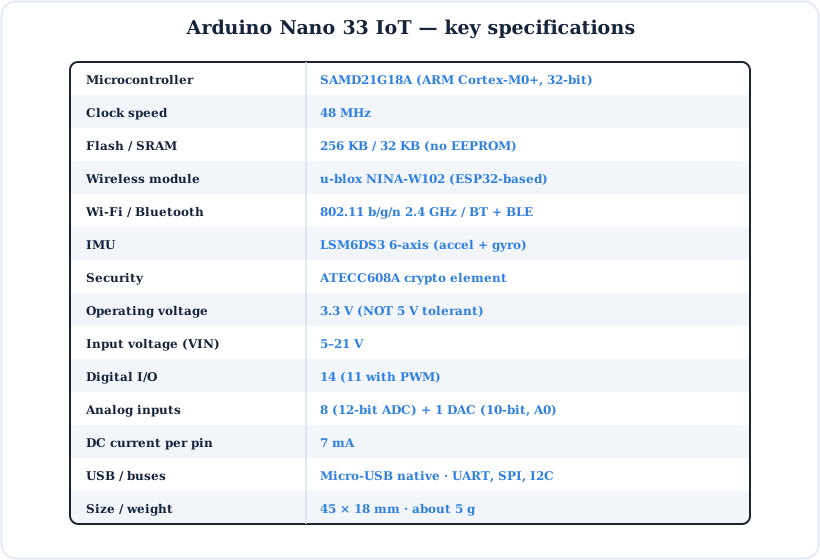
| Parameter | Value |
|---|---|
| Microcontroller | Microchip SAMD21G18A, 32-bit ARM Cortex-M0+ |
| Clock speed | 48 MHz |
| Flash / SRAM | 256 KB / 32 KB (no EEPROM) |
| Wireless | u-blox NINA-W102: Wi-Fi 802.11 b/g/n 2.4 GHz, Bluetooth + BLE |
| Sensors / security | LSM6DS3 6-axis IMU · ATECC608A crypto element |
| Operating voltage | 3.3 V (I/O not 5 V tolerant) |
| Input voltage (VIN) | 5–21 V |
| Digital I/O pins | 14 (11 with PWM, counting A2/A3/A5) |
| Analog inputs | 8 (A0–A7), 12-bit ADC |
| Analog output | 1 × 10-bit DAC on A0 |
| DC current per I/O pin | 7 mA |
| Buses | USB (native), UART (Serial1), SPI, I2C |
| Size / weight | 45 × 18 mm · about 5 g |
| Board SKU | ABX00027 (ABX00032 = version with headers) |
Key Terms — Glossary
| Term | Meaning |
|---|---|
| SAMD21 | Microchip's 32-bit ARM Cortex-M0+ microcontroller family; the G18A version has 48 pins, 256 KB flash and 32 KB SRAM. |
| Cortex-M0+ | ARM's smallest, most energy-efficient 32-bit CPU core. |
| NINA-W102 | u-blox Wi-Fi/Bluetooth module built around an ESP32, with its own flash and PCB antenna. |
| WiFiNINA | Arduino library that controls the NINA module over SPI for Wi-Fi networking. |
| BLE / GATT | Bluetooth Low Energy; data is organised as services and characteristics (the GATT profile). |
| IMU | Inertial Measurement Unit — accelerometer + gyroscope (LSM6DS3 here). |
| Secure element | A chip (ATECC608A) that stores cryptographic keys in hardware so they cannot be copied. |
| SERCOM | SAMD21 serial block that can be configured as UART, SPI or I2C. |
| DAC | Digital-to-analog converter — outputs a real voltage (A0 on this board). |
| 5 V tolerant | A pin that survives 5 V signals. Nano 33 IoT pins are not. |
| VUSB jumper | Solder pads on the back that connect USB 5 V to the 5V pin when bridged. |
| Castellated pads | Half-cut plated holes on the board edge, so the module can be soldered flat onto another PCB. |
Frequently Asked Questions
Quick answers to the questions people ask most about the Arduino Nano 33 IoT.
What is the Arduino Nano 33 IoT?
A small 45 × 18 mm board in the classic Nano footprint that combines a 32-bit SAMD21 Cortex-M0+ at 48 MHz with a u-blox NINA-W102 Wi-Fi/Bluetooth module, an LSM6DS3 6-axis IMU and an ATECC608A crypto chip. It is built for connected IoT projects and runs on 3.3 V logic.
What microcontroller does the Arduino Nano 33 IoT use?
The Microchip SAMD21G18A: a 32-bit ARM Cortex-M0+ at 48 MHz with 256 KB flash, 32 KB SRAM, a 12-bit ADC, a 10-bit DAC, six SERCOM serial ports, PWM timers and native USB. The NINA-W102 contains its own ESP32, but that chip only runs the radio firmware.
Is the Arduino Nano 33 IoT 5 V tolerant?
No. The pins are 3.3 V only, and 5 V on a pin can damage the SAMD21. Use a resistor voltage divider for 5 V signals coming into the board and a level shifter for two-way signals such as 5 V I2C.
Which pins are PWM on the Arduino Nano 33 IoT?
Eleven pins: D2, D3, D5, D6, D9, D10, D11, D12, A2, A3 and A5, all using analogWrite(). A0 also has a true 10-bit DAC that outputs a real analog voltage instead of PWM.
How does the Arduino Nano 33 IoT connect to Wi-Fi?
The SAMD21 sends commands over SPI to the NINA-W102, which runs the 2.4 GHz 802.11 b/g/n radio. In your sketch, use the WiFiNINA library: call WiFi.begin(ssid, password), wait for WL_CONNECTED, then use WiFiClient, WiFiServer or UDP. 5 GHz networks are not supported.
Can the Nano 33 IoT use Wi-Fi and Bluetooth at the same time?
Not with the standard libraries. WiFiNINA and ArduinoBLE share the single NINA-W102 radio, so a sketch uses one at a time. To switch, end one stack (for example BLE.end()) before starting the other.
Why does the 5V pin on the Nano 33 IoT give no voltage?
It is disconnected by default. The 5V pin only carries USB 5 V after you bridge the VUSB solder jumper on the underside, and it never outputs 5 V when the board runs from VIN. Regulated 3.3 V is always available on the 3V3 pin.
How do I program the Arduino Nano 33 IoT?
Install Arduino SAMD Boards in the Boards Manager, select Arduino Nano 33 IoT and its port, and click Upload. The SAMD21's native USB and bootloader mean no extra programmer is needed. If the port disappears, double-tap RESET to force bootloader mode and upload again.
What is the difference between the Nano 33 IoT and Nano 33 BLE?
The Nano 33 IoT has a SAMD21 Cortex-M0+ plus a NINA-W102, so it has both Wi-Fi and Bluetooth and a 6-axis IMU. The Nano 33 BLE uses an nRF52840 Cortex-M4F at 64 MHz with 1 MB flash and a 9-axis IMU, but has Bluetooth LE only and no Wi-Fi. Both are 3.3 V boards with the same pin layout.
What is the ATECC608A on the Nano 33 IoT used for?
It is a crypto authentication chip on the I2C bus (address 0x60). It stores private keys in tamper-resistant hardware and performs cryptographic operations, so the board can log in securely to Arduino IoT Cloud, AWS IoT or Azure IoT with certificates, using the ArduinoECCX08 library.
Conclusion & Key Takeaways
The Arduino Nano 33 IoT gives you a 32-bit ARM chip, Wi-Fi, Bluetooth, a motion sensor and hardware security in the tiny Nano footprint. Respect the 3.3 V limit and it's one of the easiest ways to put a project on the internet.
SAMD21
48 MHz, 256 KB flash.
Wi-Fi + BLE
NINA-W102, one at a time.
3.3 V only
Not 5 V tolerant, 7 mA/pin.
14 + 8 pins
11 PWM, 12-bit ADC, DAC.
IMU + crypto
LSM6DS3 & ATECC608A.
Native USB
Double-tap RESET to rescue.